
User's Manual
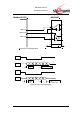
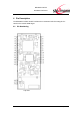
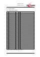
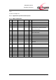
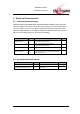
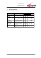
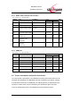
Table Of Contents
- Introduction
- Block Diagram
- Application Interface
- Pin Description
- Electrical Characteristics
- Mechanical Characteristics
- Approvals/Certifications
- Related Documents
- Ordering Information
- History

BlueMod+C11/G2
Hardware Reference
www.stollmann.de Page 20 of 42
5.3.2 GPIO, JTAG; Serial IF and Test Pins
Vcc = 3.3V, T
amb
= - 40°C to +85°C
Symbol
Item
Condition
Limit
Unit
Min
Max
V
IL
Low-Level Input Voltage
-0.3
0.8
V
V
IH
High-Level Input Voltage
2.0
5.5
V
V
OL
Low-Level Output Voltage
I
OL
< 8mA
-
0.4
V
V
OH
High-Level Output Voltage
I
OH
< 8mA
VCC-0.4
-
V
I
O1
Output Current
GPIO(5,6,15)
-
16
mA
I
O2
Output Current
GPIO(10,8), TXD,
/JTAG-RES
-
2
mA
I
O3
Output Current
Other PIO
except USB
8
Note: Please refer to ATMEL AT91SAM7S data sheet for more specific information
5.3.3 USB Pins
Vcc = 3.3V, T
amb
= - 40°C to +85°C
Symbol
Item
Condition
Limit
Unit
Min
Max
V
IL
Low-Level Input Voltage
0.8
V
V
IH
High-Level Input Voltage
2.0
V
V
DI
Diff. Input Sensitivity
0.2
V
V
CM
Common Mode Range
0.8
2.5
V
V
OL
Low-Level Output Voltage
R
L
= 1.425k to 3V6
0.0
0.3
V
V
OH
High-Level Output Voltage
R
L
= 14.25k to GND
2.8
3.6-
V
5.4 Power consumption and power down modes
To reduce power consumption of the BlueMod+C11/G2 power down modes can be
activated automatically by the BlueMod+C11/G2 (controlled by parameter settings).
If no Bluetooth connection is established, the following states are implemented, the
activation of these states can be controlled by the parameters bpsm and pwd.
For more details please refer to the BlueMod+C11/G2 software manual.