
User's Manual
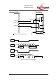
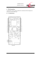
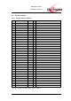
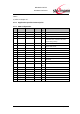
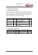
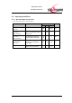
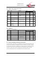
Table Of Contents
- Introduction
- Block Diagram
- Application Interface
- Pin Description
- Electrical Characteristics
- Mechanical Characteristics
- Approvals/Certifications
- Related Documents
- Ordering Information
- History

BlueMod+C11/G2
Hardware Reference
www.stollmann.de Page 17 of 42
Notes:
a) refer to Chapter 3.7
4.2.2 Application Specific Pin Description
4.2.3 SPP Configuration
Pin
Pin Name
SPP function
Type
Ac-
tive
Description
A11
GPIO8
Reserved
I-PU
A12
GPIO10
Reserved
I-PU
A13
GPIO7
/LED1
O
L
Device ready
A14
GPIO9
/LED2
O
L
Bluetooth connected. Active if a Bluetooth
connection exists. Inactive in idle state.
Flashes during startup.
C1
GPIO14
/RTC-OUT
O
L
DSR in DCE mode DTR in DTE mode
C2
GPIO15
/DCD
I/O-PU
L
Data Carrier Detect input in DTE mode,
output in DCE mode
C3
GPIO13
/RTC-IN
I-PU
L
DTR in DCE mode DSR in DTE mode
C4
/RTS
I-PU
L
Request to send
C5
/CTS
O
L
Clear to send
C6
RXD
O
Receive Data
C7
TXD
I
Transmit Data
C8
GPIO6
/RI
I/O-PU
Ring Indicator input in DTE mode, output in
DCE mode
C9
GPIO5
Reserved
I-PU
C10
GPIO4
DTE-/DCE
I-PD
47k
PD
DTE DCE mode selector
C13
VCC
VCC
P
+3.3V Power
C14
GND
GND
P
GND
C15
GND
GND
P
GND
C16
VCC
VCC
P
+3.3V Power
A1
/EXT_RES
/EXT_RES
I
L
Reset low active
C11
USB_DM
Do not connect
C12
USB_DP
Do not connect