
User's Manual


1.07work/09.2003 BlueRS+ manual
2. Installation
© Stollmann Entwicklungs- und Vertriebs-GmbH 5
2.3 Displays and control elements BlueRS+C2-MF5 desktop model
For interfacing the module version please refer to the appendix.
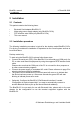
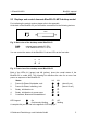
At the back of the BlueRS+C2 you will find the connectors for the following devices:
Fig. 2: Back view of the desktop model BlueRS+C2
PWR: external power supply (5V DC)
DTE: V.24 interface for DTE, i.e. a PC
You can control the status of the BlueRS+C2 via two LEDs at the front side.
Fig. 3: Front view of the desktop model BlueRS+C2
Both of the LEDs, L1 (green) and L2 (yellow), show the overall status of the
BlueRS+C2 in coded form. The following list describes the view for an error free
power on sequence of the BlueRS+C2.
Status L1 L2
1. Power-On-Phase, Bootloader, wait Θ Θ (about 2 sec)
2. Power-On-Phase, Initializing, wait Θ O (about 10 sec)
3. Ready, Initialization ok ⊗ O
4. Ready, Initialization ok, power save ∅ O
5. Connected, Bluetooth link established ⊗ ⊗
LED Legend: ⊗ On, O Off
Θ Continuously blinking, ∅ flashing
A complete list you can find in the appendix "LED displays".
DTE
PWR
L1 L2