
User's Manual

BlueRS+ manual 1.07work/09.2003
6. Appendix
44 © Stollmann Entwicklungs- und Vertriebs-GmbH
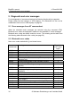
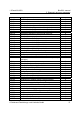
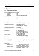
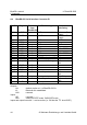
A4: BlueRS+C2 Serial Interface Connector P1
P1-Pin Signal Direction
from
BlueRS+C2
BlueRS+C2 usage External
interfacing
1 GND I 0V-Power 0V Power
supply
2 VCC I +5V-Power +5V Power
supply
3 GND GND GND
4 TXD~ I
5 GND GND GND
6 RXD~ O
7 ID2 O GND NC or READ
8 RTS~ I
9 ID1 O GND NC or READ
10 CTS~ O
11 RESET I RESET active low (OC) NC
12 DTR~ I
13 L3~ (UA0) O (internal 10k Pull up) NC or status
info
14 DCD~ O
15 RI~ O
16 DSR~ O
17 UA~ O User Output 1 NC or status
info
18 UE~ I User Input 1 10k Pull up
19 UA2 O User Output 2 NC or status
info
20 UE2 I User Input 2 GND
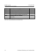
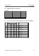
Outputs:
UA: default: similar to L1 of BlueRS+C2-Dx
L3: Bluetooth link established
UA2: reserved
Inputs:
UE: reserved
UE2: select DCE/DTE mode. GND=DCE mode.
Inputs and output lines with '~' are low active (i.e. ON has the TTL level 0VDC)