
User's Manual
Stollmann
E + V GmbH
BlueMod+B20
Hardware reference
Author: bg Date of Saving: 28.03.07 Ref: BlueMod+B20_HWreference_V101.doc Revision: 1.00 Page 19 of 19
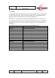
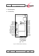
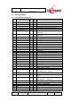
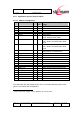
4.2.2 Application Specific Pin Description
4.2.2.1 SPP Pin Configuration
No Pin Name
Dir ac-
tive
BlueMod+B20 SPP configuration
usage
1 NC
Not Connected
2 GND - - Ground
3 PIO0 or RXEN I/O H PIO/Control output for external LNA
4 PIO1 or TXEN I/O H PIO/Control output for ext. PA (class1)
5 LED1# O L Status LED 1
6 DCD# I/O L Data Carrier Detect Input in DTE
mode; Output in DCE mode
7 RTC-IN# I L DSR – Data Set Ready in DTE mode;
DTR – Data Terminal Ready in DCE
mode
8 RTC-OUT# O L DSR – Data Set Ready in DCE mode;
DTR – Data Terminal Ready in DTE
mode
9 RI# or SCL
1
I/O - RING Input in DTE mode; Output in
DCE mode or I
2
C Serial Clock
10 SDA
1
I/O - I
2
C Serial Data
11 WP
1
O - I
2
C Write Protect
12 LED2# O L Status LED 2
13 reserved
14 reserved
21 GND - - Ground
22 VSUP - - 3.3V Supply Voltage
23 UART_RX I - UART Asynchronous Receive Data
24 UART_RTS# O L UART Request To Send
25 UART_TX O - UART Asynchronous Transmit Data
26 UART_CTS# I L UART Clear To Send
31 RESET# I L Module Reset
34 GND - - Ground
35 GND - - Ground
For USB, PCM, SPI and Analog IO pins see 4.2.1 General Pin Description, these
pins are not used in SPP configuration.
1
subject to firmware support, contact Stollmann for current status.