
User's Manual

Stollmann
E + V GmbH
BlueMod+B20
Hardware reference
Author: bg Date of Saving: 28.03.07 Ref: BlueMod+B20_HWreference_V101.doc Revision: 1.00 Page 14 of 14
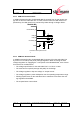
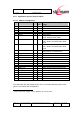
3.7 PCM Interface
PCM or Pulse Code Modulation is a sampling technique for digitising analogue sig-
nals.
The PCM interface for voice applications is provided via the PCM_OUT, PCM_IN,
PCM_CLK and PCM_SYNC pins.
The PCM interface can act as master or as slave device.
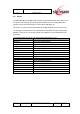
In master mode, clock frequencies of 128kHz, 256kHz or 512kHz can be generated,
when using the internal 4MHz clock. In slave mode, clock frequencies up to
2048kHz are accepted.
The Frame Clock is 8kHz. Long and Short Frame Sync are supported.
BlueMod+B20 interfaces directly to PCM audio devices including the following:
• Qualcom MSM3000 series and MSM5000 series CDMA base band devices
• OKI MSM7705 four channel A-law and µ-law codec
• Motorola MC145481 8-bit A-law and µ-law codec
• Motorola MC145483 13-bit linear codec
• STW 5093 5094 14-bit linear codec
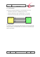
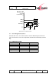
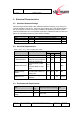
3.8 USB Interface
3.8.1 D+, D-
The BlueMod+B20 contains a full speed USB version 1.1 compliant interface capa-
ble of directly driving a USB cable. The BlueMod+B20 operates as a USB peripheral
and responds to requests from a USB master host controller.
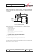
3.8.2 USB Pull-Up Resistor
In self powered mode a 1.5KΩ pull up resistor needs to be connected between PIO2
and the USB D+ line. This pulls the USB D+ line high when the BlueMod+B20 is
ready for enumeration, signalling to the host controller that the BlueMod+B20 is a
full speed (12Mbps) USB device.
In bus powered mode an internal pull up resistor can be used. For details see SW
description.