
Technical Manual

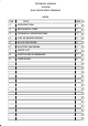

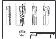
Table Of Contents
- GENERAL INDEX
- 1 INTRODUCTION
- 2 MECHANICAL VIEW
- 3 TECHNICAL SPECIFICATIONS
- 3.1 Operating frequencies
- 3.2 Transmitter output power
- 3.3 Reference sensitivity
- 3.4 Antenna
- 3.5 Audio characteristics
- 3.5.1 Microphone
- 3.5.1.1 Microphone sensitivity
- 3.5.1.1.1 Microphone electric level
- 3.5.1.1.2 Microphone distorsion
- 3.5.1.2 Buzzer
- 3.5.1.2.1 Acoustic pressure of the buzzer
- 3.5.1.3 Vibrator
- 3.6 Device voltage supply
- 3.6.1 Power consumption
- 3.7 Keypad
- 3.8 Display
- 3.9 Data service
- 3.10 Software functionality and user interface
- 3.11 Electrical interface
- 3.11.1 Bottom connector
- 3.11.2 SIM
- 3.11.3 Test connector
- 3.11.4 RF signals connector
- 3.11.5 DAI connector
- 3.12 Physical characteristics
- 3.13 Dimensions
- 3.14 Weight
- 3.15 Figures
- 4 LIST OF MODIFICATIONS
- 5 BLOCK DIAGRAMS
- 6 ELECTRIC DIAGRAMS
- CS710c GSM Radio board page 1/3
- CS710c GSM Radio board page 2/3
- CS710c GSM Radio board page 3/3
- CS680b Microphone Input & GS codec 1/15
- CS680b GSM uP, memory & RTC 2/15
- CS680b GAIM 3/15
- CS680b Power Supply & Reset 4/15
- CS680b Keyboard & display connectors 5/15
- CS680b SIM interface 6/15
- CS680b GSM radio connector 7/15
- CS680b Battery charge 8/15
- CS680b Bottom connector 9/15
- CS680b GS uP 10/15
- CS680b GS uP 11/15
- CS680b GUM ASIC 12/15
- CS680b GS vocoder 13/15
- CS680b BB2 ASIC 14/15
- CS680b GS radio connector 15/15
- CS661c Rx car kit switch & RF ampl. 1/9
- CS661c Rx phase shifter, IF filter, AGC 2/9
- CS661c Tx AGC and IF filter 3/9
- CS661c Tx upconverter, driver 4/9
- CS661c Tx power amplif, ADC multiplexer 5/9
- CS661c RF synthesizer 6/9
- CS661c General Power Supply 7/9
- CS661c Tx drv. & power ampl. p.supp 8/9
- CS661c BB connector & GSM ant. switch 9/9
- CS760 Optical Sensor Board 1/1
- 7 PARTS LIST
- 8 PHOTOS AND ASSEMBLIES
- 9 USER GUIDE

Rev. 1Telital S.p.A.
TECHNICAL MANUAL
GS/GSM
DUAL MODE USER TERMINAL
Page 2 of 13
3.1 Operating frequencies
3.1.1 GSM
The GSM operating frequencies are:
TX frequencies: 890.2 914.8 MHz
RX frequencies: 935.2 959.8 MHz
The channel (ARFCN) are numbered from 1 to 124 and frequency offset between TX and
RX frequency is 45 MHz.
3.1.2 GLOBALSTAR
The satellite operating frequencies are the standard Globalstar frequencies.
TX frequencies: 1618.11 MHz
Bandwidth: 15.99MHz
Channel bandwidth: 1.23MHz
Minimum channel shift: 30KHz
Number of shift: 0 511
Number of preferred channels: 13
Preferred channels: 4, 45, 86, 127, 168, 209, 250,
291, 332, 373, 414, 455, 496.
Rx frequencies: 2491.77 MHz
Bandwidth: 15.99MHz
Channel bandwidth: 1.23MHz
Minimum channel shift: 123KHz
Number of shift: 0 127
Number of preferred channels: 13
Preferred channels: 3, 13, 23, 33, 43, 53, 63, 73,
83, 93, 103, 113, 123.
3.2 Transmitter output power
3.2.1 GSM
a) RF power on 50 Ohm
The GSM section of the DMUT is a class 4 radiotelephone according to standard ETSI reg-
ulation that fix the limit at 2 Watts (+33dBm) on 50 Ohm;
In normal test conditions the transmitter nominal power range is between +31.5 dBm and
+32.5 dBm on 50 Ohm.
With a supply voltage range between 6.7V and 8.4V and temperature range between
–10°C and +55°C the transmitter power range is between +30.5 dBm and +32.5 dBm on
50 Ohm.
b) ERP power
Not supplied in the GSM specification.
The EIRP power will be measured in anechoic chamber.