
Technical Manual

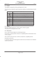
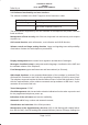
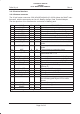
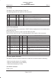
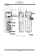
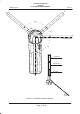
Table Of Contents
- GENERAL INDEX
- 1 INTRODUCTION
- 2 MECHANICAL VIEW
- 3 TECHNICAL SPECIFICATIONS
- 3.1 Operating frequencies
- 3.2 Transmitter output power
- 3.3 Reference sensitivity
- 3.4 Antenna
- 3.5 Audio characteristics
- 3.5.1 Microphone
- 3.5.1.1 Microphone sensitivity
- 3.5.1.1.1 Microphone electric level
- 3.5.1.1.2 Microphone distorsion
- 3.5.1.2 Buzzer
- 3.5.1.2.1 Acoustic pressure of the buzzer
- 3.5.1.3 Vibrator
- 3.6 Device voltage supply
- 3.6.1 Power consumption
- 3.7 Keypad
- 3.8 Display
- 3.9 Data service
- 3.10 Software functionality and user interface
- 3.11 Electrical interface
- 3.11.1 Bottom connector
- 3.11.2 SIM
- 3.11.3 Test connector
- 3.11.4 RF signals connector
- 3.11.5 DAI connector
- 3.12 Physical characteristics
- 3.13 Dimensions
- 3.14 Weight
- 3.15 Figures
- 4 LIST OF MODIFICATIONS
- 5 BLOCK DIAGRAMS
- 6 ELECTRIC DIAGRAMS
- CS710c GSM Radio board page 1/3
- CS710c GSM Radio board page 2/3
- CS710c GSM Radio board page 3/3
- CS680b Microphone Input & GS codec 1/15
- CS680b GSM uP, memory & RTC 2/15
- CS680b GAIM 3/15
- CS680b Power Supply & Reset 4/15
- CS680b Keyboard & display connectors 5/15
- CS680b SIM interface 6/15
- CS680b GSM radio connector 7/15
- CS680b Battery charge 8/15
- CS680b Bottom connector 9/15
- CS680b GS uP 10/15
- CS680b GS uP 11/15
- CS680b GUM ASIC 12/15
- CS680b GS vocoder 13/15
- CS680b BB2 ASIC 14/15
- CS680b GS radio connector 15/15
- CS661c Rx car kit switch & RF ampl. 1/9
- CS661c Rx phase shifter, IF filter, AGC 2/9
- CS661c Tx AGC and IF filter 3/9
- CS661c Tx upconverter, driver 4/9
- CS661c Tx power amplif, ADC multiplexer 5/9
- CS661c RF synthesizer 6/9
- CS661c General Power Supply 7/9
- CS661c Tx drv. & power ampl. p.supp 8/9
- CS661c BB connector & GSM ant. switch 9/9
- CS760 Optical Sensor Board 1/1
- 7 PARTS LIST
- 8 PHOTOS AND ASSEMBLIES
- 9 USER GUIDE

Rev. 1Telital S.p.A.
TECHNICAL MANUAL
GS/GSM
DUAL MODE USER TERMINAL
Page 8 of 13
3.11 Electrical interface
3.11.1 Bottom connector
The 20 pin bottom connector SO2 HIROSE MQ168–QC–20P/4 allows the DMUT inter-
facement with the accessories as Car Kit, Battery charger, Data Terminal Adapter.
The four pins from 21 to 24 allows the connection of battery pack.
PIN NAME A/D IN/OUT DESCRIPTION
1 +VBATT A IN +10.4V from battery charger
2 DM_TX D OUT TX serial line debug monitor G*edge
3 DM_RX D IN RX serial line debug monitor G* edge
4 DM_RTS D OUT Request To Send debug monitor G*edge
5 DM_CTS D IN Clear To Send debug monitor G*edge
6 DATA_GS_TX D OUT Data transmission line in G* mode
7 DATA_GS_RX D IN Data reception line in G*mode
8 GSM_TX D OUT Data transmission and monitor line in GSM
mode
9 GSM_RX D IN Data reception and monitor line in GSM
mode
10 AXE D IN External device connection signal
11 SW_BATT A OUT Power supplied to external device con-
nected with AXE = 0 V
12 CAR_PCM_CLK D OUT CLOCK PCM connection to CAR KIT
13 CAR_PCM_DOUT D OUT Data OUT PCM connection to CAR KIT
14 CAR_PCM_DIN D IN Data IN PCM connection to CAR KIT
15 CAR_PCM_SYNC D OUT SYNC PCM connection to CAR KIT
16 GS/GSM D OUT Signalling for the DMUT operative mode
GSM or G*
17 ON–OFF D IN Signal for DMUT remote power on
18 CAR_AUDIO_IN D IN Analog audio from CAR KIT
19 CAR_AUDIO_OUT – –––– Analog Audio to CAR KIT
20 GND A –––– Ground
21 NTC A –––– Pin used for reading the internal tempera-
ture of battery pack by an NTC or other
sensor.
22 GND A –––– Ground Battery pack
23 +VBATT – –––– Positive Battery pack
24 SPARE – ––––
Legend: A: Analog; D: Digital 0 3V CMOS