
Technical Manual

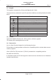
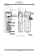
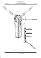
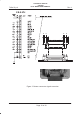
Table Of Contents
- GENERAL INDEX
- 1 INTRODUCTION
- 2 MECHANICAL VIEW
- 3 TECHNICAL SPECIFICATIONS
- 3.1 Operating frequencies
- 3.2 Transmitter output power
- 3.3 Reference sensitivity
- 3.4 Antenna
- 3.5 Audio characteristics
- 3.5.1 Microphone
- 3.5.1.1 Microphone sensitivity
- 3.5.1.1.1 Microphone electric level
- 3.5.1.1.2 Microphone distorsion
- 3.5.1.2 Buzzer
- 3.5.1.2.1 Acoustic pressure of the buzzer
- 3.5.1.3 Vibrator
- 3.6 Device voltage supply
- 3.6.1 Power consumption
- 3.7 Keypad
- 3.8 Display
- 3.9 Data service
- 3.10 Software functionality and user interface
- 3.11 Electrical interface
- 3.11.1 Bottom connector
- 3.11.2 SIM
- 3.11.3 Test connector
- 3.11.4 RF signals connector
- 3.11.5 DAI connector
- 3.12 Physical characteristics
- 3.13 Dimensions
- 3.14 Weight
- 3.15 Figures
- 4 LIST OF MODIFICATIONS
- 5 BLOCK DIAGRAMS
- 6 ELECTRIC DIAGRAMS
- CS710c GSM Radio board page 1/3
- CS710c GSM Radio board page 2/3
- CS710c GSM Radio board page 3/3
- CS680b Microphone Input & GS codec 1/15
- CS680b GSM uP, memory & RTC 2/15
- CS680b GAIM 3/15
- CS680b Power Supply & Reset 4/15
- CS680b Keyboard & display connectors 5/15
- CS680b SIM interface 6/15
- CS680b GSM radio connector 7/15
- CS680b Battery charge 8/15
- CS680b Bottom connector 9/15
- CS680b GS uP 10/15
- CS680b GS uP 11/15
- CS680b GUM ASIC 12/15
- CS680b GS vocoder 13/15
- CS680b BB2 ASIC 14/15
- CS680b GS radio connector 15/15
- CS661c Rx car kit switch & RF ampl. 1/9
- CS661c Rx phase shifter, IF filter, AGC 2/9
- CS661c Tx AGC and IF filter 3/9
- CS661c Tx upconverter, driver 4/9
- CS661c Tx power amplif, ADC multiplexer 5/9
- CS661c RF synthesizer 6/9
- CS661c General Power Supply 7/9
- CS661c Tx drv. & power ampl. p.supp 8/9
- CS661c BB connector & GSM ant. switch 9/9
- CS760 Optical Sensor Board 1/1
- 7 PARTS LIST
- 8 PHOTOS AND ASSEMBLIES
- 9 USER GUIDE

Rev. 1Telital S.p.A.
TECHNICAL MANUAL
GS/GSM
DUAL MODE USER TERMINAL
Page 6 of 13
3.10Software functionality and user interface
The software installed in the DMUT supports all the functions in table.
Radio interface
Radio Protocol Phase 2
Speech Coding Full Rating
SIM SIM 3/5 volt
SIM Toolkit compliant GSM 11.14
The functionalities supported by the user interface of the telephone are phase 2 and are
listed as follows:
Management of local security, with SIM Lock, keyboard lock and security code request
at power–up;
Call control function, with call duration, cost indication and UDUB function;
Volume control and ringer setting function, ringer and signaling tones with possibility
of activation of alarm also with telephone powered off;
Display management with contrast level regulation and duration of backlight;
Messages visualized setup in ready state and its language, visualization of the IMEI and
the software release of the telephone;
Font Management uppercase/lowercase and international (no Chinese);
SIM related functions, as the activation/deactivation of the numbers in notebook FDN,
ADN and PIN. Extension to the PIN2 of the possibility of insertion of PUK2 in case of lock.
The telephone supports besides the functionalities of class 2 of the SIM Application Toolkit
with the implementation of the relative commands and procedures at MMI level. Imple-
mentation of two levels SIM lock.
Tones Management DTMF;
Clock Management with time and alert activation indications for the wake–up service and
for the programmed telephone power–up;
Indication of the call status and service availability;
Automatic call of busy number and automatic answer;
Visualization and selection of the GSM providers;
Management of the Supplementary Services (SS) of Call Barring (with related indica-
tion, also for SMS), Call Forwarding (with related indication), Advice of Charge, Calling Line