
Technical Manual
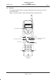
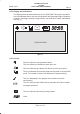
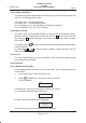
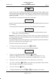
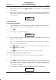

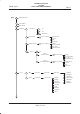
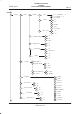
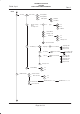
Table Of Contents
- GENERAL INDEX
- 1 INTRODUCTION
- 2 MECHANICAL VIEW
- 3 TECHNICAL SPECIFICATIONS
- 3.1 Operating frequencies
- 3.2 Transmitter output power
- 3.3 Reference sensitivity
- 3.4 Antenna
- 3.5 Audio characteristics
- 3.5.1 Microphone
- 3.5.1.1 Microphone sensitivity
- 3.5.1.1.1 Microphone electric level
- 3.5.1.1.2 Microphone distorsion
- 3.5.1.2 Buzzer
- 3.5.1.2.1 Acoustic pressure of the buzzer
- 3.5.1.3 Vibrator
- 3.6 Device voltage supply
- 3.6.1 Power consumption
- 3.7 Keypad
- 3.8 Display
- 3.9 Data service
- 3.10 Software functionality and user interface
- 3.11 Electrical interface
- 3.11.1 Bottom connector
- 3.11.2 SIM
- 3.11.3 Test connector
- 3.11.4 RF signals connector
- 3.11.5 DAI connector
- 3.12 Physical characteristics
- 3.13 Dimensions
- 3.14 Weight
- 3.15 Figures
- 4 LIST OF MODIFICATIONS
- 5 BLOCK DIAGRAMS
- 6 ELECTRIC DIAGRAMS
- CS710c GSM Radio board page 1/3
- CS710c GSM Radio board page 2/3
- CS710c GSM Radio board page 3/3
- CS680b Microphone Input & GS codec 1/15
- CS680b GSM uP, memory & RTC 2/15
- CS680b GAIM 3/15
- CS680b Power Supply & Reset 4/15
- CS680b Keyboard & display connectors 5/15
- CS680b SIM interface 6/15
- CS680b GSM radio connector 7/15
- CS680b Battery charge 8/15
- CS680b Bottom connector 9/15
- CS680b GS uP 10/15
- CS680b GS uP 11/15
- CS680b GUM ASIC 12/15
- CS680b GS vocoder 13/15
- CS680b BB2 ASIC 14/15
- CS680b GS radio connector 15/15
- CS661c Rx car kit switch & RF ampl. 1/9
- CS661c Rx phase shifter, IF filter, AGC 2/9
- CS661c Tx AGC and IF filter 3/9
- CS661c Tx upconverter, driver 4/9
- CS661c Tx power amplif, ADC multiplexer 5/9
- CS661c RF synthesizer 6/9
- CS661c General Power Supply 7/9
- CS661c Tx drv. & power ampl. p.supp 8/9
- CS661c BB connector & GSM ant. switch 9/9
- CS760 Optical Sensor Board 1/1
- 7 PARTS LIST
- 8 PHOTOS AND ASSEMBLIES
- 9 USER GUIDE

TECHNICAL MANUAL
GS/GSM
DUAL MODE USER TERMINAL
Rev. 0
Telital S.p.A.
Page6of12
By pressing ”C” the last character will be cancelled, and if you keep ”C” pressed
for longer time all characters will be cancelled.
When the desired location appears on the display, press
(SEND) to place the
call.
When recalling a memory location not available on the SIM card the following will
be displayed:
No record
New record?
ADN Memories: Available memory locations in SIM card. Available quantity
depends on the SIM card you have chosen.
FDN Memories: Also contained in the SIM card with same features as ADN
memories. Activation of FDN memories must be performed from the menu and
by entering the PIN2 code which is not always supplied by the network operator.
9.1.6 Function menu
Press "M" key followed by the number key corresponding with the desired menu
number or,
Press "M" key to going to the menu.
Press
and or press the "M" key to browse the menus.
Confirm the access on the desired menu by pressing (SEND) key.
To exit from menu without save the settings press
(END) key.
To exit from menu and save the settings press (SEND) key.
If a ”Proactive” SIM is inserted into a DMUT, a menu item 0 will be displayed.
By selecting this item, access will be given to the SIM Toolkit services supplied by
the network operator.
After 3 minutes of inactivity on the menu operations, the operative condition will
be automatically restored.
The following diagrams show the function menu structure.