
Technical Manual
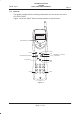
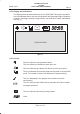
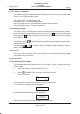
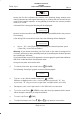

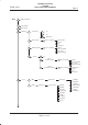
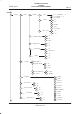
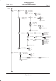
Table Of Contents
- GENERAL INDEX
- 1 INTRODUCTION
- 2 MECHANICAL VIEW
- 3 TECHNICAL SPECIFICATIONS
- 3.1 Operating frequencies
- 3.2 Transmitter output power
- 3.3 Reference sensitivity
- 3.4 Antenna
- 3.5 Audio characteristics
- 3.5.1 Microphone
- 3.5.1.1 Microphone sensitivity
- 3.5.1.1.1 Microphone electric level
- 3.5.1.1.2 Microphone distorsion
- 3.5.1.2 Buzzer
- 3.5.1.2.1 Acoustic pressure of the buzzer
- 3.5.1.3 Vibrator
- 3.6 Device voltage supply
- 3.6.1 Power consumption
- 3.7 Keypad
- 3.8 Display
- 3.9 Data service
- 3.10 Software functionality and user interface
- 3.11 Electrical interface
- 3.11.1 Bottom connector
- 3.11.2 SIM
- 3.11.3 Test connector
- 3.11.4 RF signals connector
- 3.11.5 DAI connector
- 3.12 Physical characteristics
- 3.13 Dimensions
- 3.14 Weight
- 3.15 Figures
- 4 LIST OF MODIFICATIONS
- 5 BLOCK DIAGRAMS
- 6 ELECTRIC DIAGRAMS
- CS710c GSM Radio board page 1/3
- CS710c GSM Radio board page 2/3
- CS710c GSM Radio board page 3/3
- CS680b Microphone Input & GS codec 1/15
- CS680b GSM uP, memory & RTC 2/15
- CS680b GAIM 3/15
- CS680b Power Supply & Reset 4/15
- CS680b Keyboard & display connectors 5/15
- CS680b SIM interface 6/15
- CS680b GSM radio connector 7/15
- CS680b Battery charge 8/15
- CS680b Bottom connector 9/15
- CS680b GS uP 10/15
- CS680b GS uP 11/15
- CS680b GUM ASIC 12/15
- CS680b GS vocoder 13/15
- CS680b BB2 ASIC 14/15
- CS680b GS radio connector 15/15
- CS661c Rx car kit switch & RF ampl. 1/9
- CS661c Rx phase shifter, IF filter, AGC 2/9
- CS661c Tx AGC and IF filter 3/9
- CS661c Tx upconverter, driver 4/9
- CS661c Tx power amplif, ADC multiplexer 5/9
- CS661c RF synthesizer 6/9
- CS661c General Power Supply 7/9
- CS661c Tx drv. & power ampl. p.supp 8/9
- CS661c BB connector & GSM ant. switch 9/9
- CS760 Optical Sensor Board 1/1
- 7 PARTS LIST
- 8 PHOTOS AND ASSEMBLIES
- 9 USER GUIDE

TECHNICAL MANUAL
GS/GSM
DUAL MODE USER TERMINAL
Rev. 0
Telital S.p.A.
Page4of12
Net Provider
** GS/GSM DMUT **
where the first line indicates the antenna icon (flashing during network auto
search) followed by radio signal intensity (up to 4 bars) and the second line the
name of the network operator, or the gateway ID and then the service provider
name in G* mode.
If inserted PIN is wrong the following will be displayed:
PIN>
Remain X retries
where X on the second line indicates the number of possibilities left to retry correct
PIN entering.
If the wrong PIN is entered for three times the following will be displayed:
PUK>
Remain X retries
Key in * 05 *, the 8 PUK digits provided by the network operator, press
* (new PIN) * (new PIN) and then #.
Warning: If you cannot remember your PUK code or you enter a wrong one for
10 times, you have no other possibility but that of contacting the network operator
who issued your SIM card.
If you inserted the correct PUK appeares a success graphic symbol that indicates
that PUK is valid and then the operative mask.
Now you can place and receive calls.
To switch off the unit: press and release
(POWER).
The following ”Good Bye” graphic screen will be displayed:
Good Bye!
To place a call: dial the number and press (SEND).
Mistakes in digiting have to be corrected by pressing shortly " " key.
If you keep " " key pressed for longer time, all digits will be cancelled.
Emergency calls can be placed also if the SIM card is not inserted.
To receive a call: Press
(SEND) or any other key if programmed in the menu.
When using the handset: pick up the handset.
To end a call: Press
(END).
To adjust listening level: Press
and long during conversation.