
Technical Manual
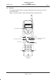
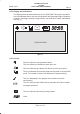
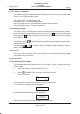
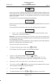

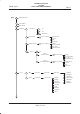
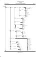
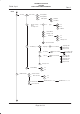
Table Of Contents
- GENERAL INDEX
- 1 INTRODUCTION
- 2 MECHANICAL VIEW
- 3 TECHNICAL SPECIFICATIONS
- 3.1 Operating frequencies
- 3.2 Transmitter output power
- 3.3 Reference sensitivity
- 3.4 Antenna
- 3.5 Audio characteristics
- 3.5.1 Microphone
- 3.5.1.1 Microphone sensitivity
- 3.5.1.1.1 Microphone electric level
- 3.5.1.1.2 Microphone distorsion
- 3.5.1.2 Buzzer
- 3.5.1.2.1 Acoustic pressure of the buzzer
- 3.5.1.3 Vibrator
- 3.6 Device voltage supply
- 3.6.1 Power consumption
- 3.7 Keypad
- 3.8 Display
- 3.9 Data service
- 3.10 Software functionality and user interface
- 3.11 Electrical interface
- 3.11.1 Bottom connector
- 3.11.2 SIM
- 3.11.3 Test connector
- 3.11.4 RF signals connector
- 3.11.5 DAI connector
- 3.12 Physical characteristics
- 3.13 Dimensions
- 3.14 Weight
- 3.15 Figures
- 4 LIST OF MODIFICATIONS
- 5 BLOCK DIAGRAMS
- 6 ELECTRIC DIAGRAMS
- CS710c GSM Radio board page 1/3
- CS710c GSM Radio board page 2/3
- CS710c GSM Radio board page 3/3
- CS680b Microphone Input & GS codec 1/15
- CS680b GSM uP, memory & RTC 2/15
- CS680b GAIM 3/15
- CS680b Power Supply & Reset 4/15
- CS680b Keyboard & display connectors 5/15
- CS680b SIM interface 6/15
- CS680b GSM radio connector 7/15
- CS680b Battery charge 8/15
- CS680b Bottom connector 9/15
- CS680b GS uP 10/15
- CS680b GS uP 11/15
- CS680b GUM ASIC 12/15
- CS680b GS vocoder 13/15
- CS680b BB2 ASIC 14/15
- CS680b GS radio connector 15/15
- CS661c Rx car kit switch & RF ampl. 1/9
- CS661c Rx phase shifter, IF filter, AGC 2/9
- CS661c Tx AGC and IF filter 3/9
- CS661c Tx upconverter, driver 4/9
- CS661c Tx power amplif, ADC multiplexer 5/9
- CS661c RF synthesizer 6/9
- CS661c General Power Supply 7/9
- CS661c Tx drv. & power ampl. p.supp 8/9
- CS661c BB connector & GSM ant. switch 9/9
- CS760 Optical Sensor Board 1/1
- 7 PARTS LIST
- 8 PHOTOS AND ASSEMBLIES
- 9 USER GUIDE

TECHNICAL MANUAL
GS/GSM
DUAL MODE USER TERMINAL
Rev. 0
Telital S.p.A.
Page3of12
9.1.1.2 Status indications
The status of the dual mode telephone will be given by a led on the front panel and
icons on LCD display graphic area.
LED status ON = GS operating mode;
LED status OFF = GSM operating mode;
Icon on Display for the ”GS Maintenance Required” indication;
Icon on Display for the ”GS Lock” indication.
9.1.2 Battery charger
The DMUT have a rechargeable Lithium ion battery pack and a battery charger.
When the battery charge level becomes low, the icon
shows this status and
when the icon
empty is blinking, is necessary to connect the battery charger
to the DMUT.
The graphic symbol
is shown when the telephone is operating during a battery
charge operation.
The bitmap . is shown during a battery charge operation with the
DMUT turned off.
9.1.3 Car kit
The car kit option allows to connect the DMUT to the vehicle with battery charge
and hands free functionality.
9.1.4 Operation
9.1.4.1 Minimal functionality
The following operations allows to turn on the DMUT, place a call and then turn
off the DMUT.
Insert your plug–in SIM card into the slot
Press
(POWER) for 1 second to switch on the unit
If PIN is enabled:
PIN>
SOS
If inserted PIN is correct the unit starts network auto search.
In G* mode the following will be displayed:
Searching GW
...
In GSM mode the following will be displayed:
Net Search
** GS/GSM DMUT **
at the end of the search the following will be displayed: