
Technical Manual


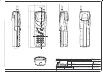
Table Of Contents
- GENERAL INDEX
- 1 INTRODUCTION
- 2 MECHANICAL VIEW
- 3 TECHNICAL SPECIFICATIONS
- 3.1 Operating frequencies
- 3.2 Transmitter output power
- 3.3 Reference sensitivity
- 3.4 Antenna
- 3.5 Audio characteristics
- 3.5.1 Microphone
- 3.5.1.1 Microphone sensitivity
- 3.5.1.1.1 Microphone electric level
- 3.5.1.1.2 Microphone distorsion
- 3.5.1.2 Buzzer
- 3.5.1.2.1 Acoustic pressure of the buzzer
- 3.5.1.3 Vibrator
- 3.6 Device voltage supply
- 3.6.1 Power consumption
- 3.7 Keypad
- 3.8 Display
- 3.9 Data service
- 3.10 Software functionality and user interface
- 3.11 Electrical interface
- 3.11.1 Bottom connector
- 3.11.2 SIM
- 3.11.3 Test connector
- 3.11.4 RF signals connector
- 3.11.5 DAI connector
- 3.12 Physical characteristics
- 3.13 Dimensions
- 3.14 Weight
- 3.15 Figures
- 4 LIST OF MODIFICATIONS
- 5 BLOCK DIAGRAMS
- 6 ELECTRIC DIAGRAMS
- CS710c GSM Radio board page 1/3
- CS710c GSM Radio board page 2/3
- CS710c GSM Radio board page 3/3
- CS680b Microphone Input & GS codec 1/15
- CS680b GSM uP, memory & RTC 2/15
- CS680b GAIM 3/15
- CS680b Power Supply & Reset 4/15
- CS680b Keyboard & display connectors 5/15
- CS680b SIM interface 6/15
- CS680b GSM radio connector 7/15
- CS680b Battery charge 8/15
- CS680b Bottom connector 9/15
- CS680b GS uP 10/15
- CS680b GS uP 11/15
- CS680b GUM ASIC 12/15
- CS680b GS vocoder 13/15
- CS680b BB2 ASIC 14/15
- CS680b GS radio connector 15/15
- CS661c Rx car kit switch & RF ampl. 1/9
- CS661c Rx phase shifter, IF filter, AGC 2/9
- CS661c Tx AGC and IF filter 3/9
- CS661c Tx upconverter, driver 4/9
- CS661c Tx power amplif, ADC multiplexer 5/9
- CS661c RF synthesizer 6/9
- CS661c General Power Supply 7/9
- CS661c Tx drv. & power ampl. p.supp 8/9
- CS661c BB connector & GSM ant. switch 9/9
- CS760 Optical Sensor Board 1/1
- 7 PARTS LIST
- 8 PHOTOS AND ASSEMBLIES
- 9 USER GUIDE

Rev. 1Telital S.p.A.
TECHNICAL MANUAL
GS/GSM
DUAL MODE USER TERMINAL
Page 3 of 13
3.2.2 GLOBALSTAR
Output power >23 dBm
+26 dBm
3.3 Reference sensitivity
3.3.1 GSM
Sensitivity on 50 Ohm
The sensitivity is according to the GSM specification for the class 4 portable terminal;
The standard ETSI regulation para 6 fix a limit of –102dBm.
The goal limit is –104 dBm for an Rx Quality < 0.2 – 0.4%.
3.3.2 GLOBALSTAR
Ref. Qualcomm specifications 80–25015–1 X6.
3.4 Antenna
3.4.1 GSM
The antenna for the GSM band is ALLGON 3576.2
3.4.2 Globalstar
The antenna for the satellite Globalstar band is composed of more parts and is assembled
on the telephone in way that can rotate on 4 positions.
The satellite antenna in its rotating stalk contains an LNA for the Rx section, the receiving
part Rx and the transmitting part Tx.
An optical sensor assembled on the body of the telephone under the antenna rotor, acti-
vates the satellite transmission when the antenna is rotated in the positions 1, 2 and 3. In
the intermediary positions the transmitter of the satellite section is always disabled.
In the position 0 the telephone works only on the GSM band.
The rotation of the antenna is prevented over the position 3.
3.5 Audio characteristics
3.5.1 Microphone
The telephone uses a microphone PRIMO type EM131S2B2.
This is inserted in a rubber gasket.
3.5.1.1 Microphone sensitivity
The typical level is 3mV typical with a –4.7dBPa signal SPL at f=1kHz
3.5.1.1.1 Microphone electric level
The typical level is >570mVrms with signal AF of 3mV @ f=1kHz.