UC864-E-AUTO UC864-AWS-AUTO Hardware User Guide 1vv0300795 Rev.
UC864-E-AUTO / AWS-AUTO Hardware User Guide 1vv0300795 Rev.11 – 2010/11/18 This document is relating to the following products: PRODUCT UC864-E-AUTO UC864-AWS-AUTO Reproduction forbidden without Telit Communications S.p.A’s. written authorization - All Rights Reserved.
UC864-E-AUTO / AWS-AUTO Hardware User Guide 1vv0300795 Rev.11 – 2010/11/18 Disclaimer The information contained in this document is the proprietary information of Telit Communications S.p.A. and its affiliates (“TELIT”). The contents are confidential and any disclosure to persons other than the officers, employees, agents or subcontractors of the owner or licensee of this document, without the prior written consent of Telit, is strictly prohibited.
UC864-E-AUTO / AWS-AUTO Hardware User Guide 1vv0300795 Rev.11 – 2010/11/18 Contents 1. OVERVIEW ............................................................................................................................................................... 6 2. MECHANICAL DIMENSIONS ............................................................................................................................... 7 2.1. 3. UC864-E-AUTO / AWS-AUTO MECHANICAL DIMENSIONS .......................................
UC864-E-AUTO / AWS-AUTO Hardware User Guide 1vv0300795 Rev.11 – 2010/11/18 11.3.1. 12. Output Lines Characteristics................................................................................................................ 51 GENERAL PURPOSE I/O ................................................................................................................................. 52 12.1. 12.2. 12.3. 12.4. 12.5. 12.6. 12.7. 12.8. LOGIC LEVEL SPECIFICATIONS .................................................
UC864-E-AUTO / AWS-AUTO Hardware User Guide 1vv0300795 Rev.11 – 2010/11/18 1. Overview The aim of this document is the description of some hardware solutions useful for developing a product with the Telit UC864-E-AUTO and UC864-AWS-AUTO modules. In this document all the basic functions of a mobile phone will be taken into account; for each one of them a proper hardware solution will be suggested and eventually the wrong solutions and common errors to be avoided will be evidenced.
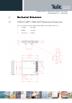
UC864-E-AUTO / AWS-AUTO Hardware User Guide 1vv0300795 Rev.11 – 2010/11/18 2. Mechanical Dimensions 2.1. UC864-E-AUTO / AWS-AUTO Mechanical Dimensions The Telit UC864-E-AUTO / AWS-AUTO module overall dimensions are: • Length: 36.2 mm • Width: 30.0 mm • Thickness: 5.1mm Reproduction forbidden without Telit Communications S.p.A’s. written authorization - All Rights Reserved.
UC864-E-AUTO / AWS-AUTO Hardware User Guide 1vv0300795 Rev.11 – 2010/11/18 3. UC864UC864-E-AUTO / AWSAWS-AUTO Module C onnections 3.1. PIN-OUT UC864-E-AUTO / AWS-AUTO uses an 80 pin Molex p.n. 53949-0878 male connector for the connections with the external applications. This connector matches the 54150-0878 models.
UC864-E-AUTO / AWS-AUTO Hardware User Guide 1vv0300795 Rev.11 – 2010/11/18 Pin Signal I/O Function Internal Pull up Type Prog. / Data + Hw Flow Control 25 C103/TXD I Serial data input (TXD) from DTE Pull-Down CMOS 2.6V 26 C104/RXD O Serial data output to DTE Pull-Up CMOS 2.6V 27 C107/DSR O Output for Data set ready signal (DSR) to DTE Pull-Down CMOS 2.6V 28 C106/CTS O Output for Clear to send signal (CTS) to DTE Pull-Up CMOS 2.
UC864-E-AUTO / AWS-AUTO Hardware User Guide 1vv0300795 Rev.11 – 2010/11/18 Pin Signal I/O Function Internal Pull up Type 62 GPIO_12 I/O GPIO12 Configurable GPIO CMOS 2.6V 63 GPIO_10/ PCM_TX I/O GPIO10 Configurable GPIO / PCM Data Output 64 GPIO_22 I/O GPIO22 Configurable GPIO 65 GPIO_18/ PCM_RX I/O GPIO18 Configurable GPIO / PCM Data input 66 GPIO_03 I/O GPIO3 Configurable GPIO CMOS 2.6V 67 GPIO_08 I/O GPIO8 Configurable GPIO CMOS 2.
UC864-E-AUTO / AWS-AUTO Hardware User Guide 1vv0300795 Rev.11 – 2010/11/18 Note: Note: If not used, almost all pins must be left disconnected.
UC864-E-AUTO / AWS-AUTO Hardware User Guide 1vv0300795 Rev.11 – 2010/11/18 4. TEMPERATURE RANGE The UC864-E-AUTO / AWS-AUTO Temperature ranges are: Reference Ambient Temperature Normal Operating -10°C to +55°C Extended Operating -20°C to +70°C Extreme Range -30°C to +85°C Storage -40°C to +85°C Reproduction forbidden without Telit Communications S.p.A’s. written authorization - All Rights Reserved.
UC864-E-AUTO / AWS-AUTO Hardware User Guide 1vv0300795 Rev.11 – 2010/11/18 4.1. Antenna Connector(s) The UC864-E-AUTO / AWS-AUTO module is designed with a 50 Ohm RF PAD that permits to interface it with an application equipped by a Rosenberger coaxial Board to board connector. The counterpart suitable is a Rosenberger 99CI106-030L5. Suggested footprint on the application side: Reproduction forbidden without Telit Communications S.p.A’s. written authorization - All Rights Reserved.
UC864-E-AUTO / AWS-AUTO Hardware User Guide 1vv0300795 Rev.11 – 2010/11/18 5. Hardware Commands 5.1. Turning ON the UC864-E-AUTO / AWS-AUTO To turn on UC864-E-AUTO / AWS-AUTO, the pad ON# must be tied low for at least 1 second and then released. The maximum current that can be drained from the ON# pad is 0,1 mA. A ON# to simple circuit do it is: R1 Q1 Power ON impulse R2 GND Reproduction forbidden without Telit Communications S.p.A’s. written authorization - All Rights Reserved.
UC864-E-AUTO / AWS-AUTO Hardware User Guide 1vv0300795 Rev.11 – 2010/11/18 5.2. Initialization and Activation state Upon turning on UC864-E-AUTO / AWS-AUTO, the module is not activated yet because the boot sequence of UC864-E-AUTO / AWS-AUTO is still going on internally. It takes about 10 seconds to complete the initializing the module internally. For this reason, it would be useless to try to access UC864-E-AUTO/ AWS-AUTO during a Initialization state as below.
UC864-E-AUTO / AWS-AUTO Hardware User Guide 1vv0300795 Rev.11 – 2010/11/18 NOTE: To check if the UC864-E-AUTO / AWS-AUTO has powered on, the hardware line PWRMON must be monitored. When PWRMON goes high, the module has powered on. NOTE: Do not use any pull up resistor on the ON/OFF# line, it is internally pulled up. Using pull up resistor may bring to latch up problems on the UC864-E-AUTO / AWS-AUTO power regulator and improper power on/off of the module.
UC864-E-AUTO / AWS-AUTO Hardware User Guide 1vv0300795 Rev.11 – 2010/11/18 5.3. Turning OFF the UC864-E-AUTO / AWS-AUTO Turning off the device can be done in three ways: • by software command (see UC864-E-AUTO / AWS-AUTO Software User Guide) • by hardware shutdown • by Hardware Unconditional Restart When the device is shut down by software command or by hardware shutdown, it issues to the network a detach request that informs the network that the device will not be reachable any more.
UC864-E-AUTO / AWS-AUTO Hardware User Guide 1vv0300795 Rev.11 – 2010/11/18 5.3.1. Shutdown by Software Command UC864-E-AUTO / AWS-AUTO can be shut down by a software command. When a shut down command is sent, UC864-E-AUTO / AWS-AUTO goes into the finalization state and finally will shut down PWRMON at the end of this state. The period of the finalization state can differ according to the situation in which the UC864-E-AUTO / AWS-AUTO is so it cannot be fixed definitely.
UC864-E-AUTO / AWS-AUTO Hardware User Guide 1vv0300795 Rev.11 – 2010/11/18 5.3.2. Hardware Shutdown To turn OFF UC864-E-AUTO / AWS-AUTO the pad ON/OFF# must be tied low for at least 2 seconds and then released. Same circuitry and timing for the power on must be used. When the hold time of ON/OFF# is above 2 seconds, UC864-E-AUTO / AWS-AUTO goes into the finalization state and finally will shut down PWRMON at the end of this state.
UC864-E-AUTO / AWS-AUTO Hardware User Guide 1vv0300795 Rev.11 – 2010/11/18 5.3.3. Hardware Unconditional Restart To unconditionally restart UC864-E-AUTO / AWS-AUTO, the pad RESET# must be tied low for at least 200 milliseconds and then released. A simple circuit to do it is: RESET# Unconditional Restart impulse GND NOTE: Do not use any pull up resistor on the RESET# line or any totem pole digital output.
UC864-E-AUTO / AWS-AUTO Hardware User Guide 1vv0300795 Rev.11 – 2010/11/18 For example: 10k 1- Let us assume you need to drive the RESET# pad with a totem pole output of a +1.8/5 V microcontroller (uP_OUT2): +1.8 / 5V 5.4. Summary of Turning ON and OFF the module Below chart describes the overall sequences for Turning ON and OFF. Reproduction forbidden without Telit Communications S.p.A’s. written authorization - All Rights Reserved.
UC864-E-AUTO / AWS-AUTO Hardware User Guide 1vv0300795 Rev.11 – 2010/11/18 6. Power Supply The power supply circuitry and board layout are a very important part in the full product design and they strongly reflect on the product overall performances. Read carefully the requirements and the guidelines that will follow for a proper design. 6.1.
UC864-E-AUTO / AWS-AUTO Hardware User Guide 1vv0300795 Rev.11 – 2010/11/18 In GSM/GPRS mode, RF transmission is not continuous and it is packed into bursts at a base frequency of about 216 Hz, and the relative current peaks can be as high as about 2A. Therefore the power supply has to be designed in order to withstand these current peaks without big voltage drops; this means that both the electrical design and the board layout must be designed for this current flow.
UC864-E-AUTO / AWS-AUTO Hardware User Guide 1vv0300795 Rev.11 – 2010/11/18 6.2. General Design Rules The principal guidelines for the Power Supply Design embrace three different design steps: 6.2.1. • the electrical design • the thermal design • the PCB layout Electrical Design Guidelines The electrical design of the power supply depends strongly on the power source where this power is drained. We will distinguish them into three categories: 6.2.1.1.
UC864-E-AUTO / AWS-AUTO Hardware User Guide 1vv0300795 Rev.11 – 2010/11/18 An example of linear regulator with 5V input is: 6.2.1.2. + 12V Input Source Power Supply Design Guidelines • The desired output for the power supply is 3.8V, hence due to the big difference between the input source and the desired output, a linear regulator is not suited and must not be used.
UC864-E-AUTO / AWS-AUTO Hardware User Guide 1vv0300795 Rev.11 – 2010/11/18 • Make sure the low ESR capacitor on the power supply output (usually a tantalum one) is rated at least 10V. • For Car applications a spike protection diode must be inserted close to the power input, in order to clean the supply from spikes. • A protection diode must be inserted close to the power input, in order to save UC864-E-AUTO / AWS-AUTO from power polarity inversion. This can be the same diode as for spike protection.
UC864-E-AUTO / AWS-AUTO Hardware User Guide 1vv0300795 Rev.11 – 2010/11/18 6.2.1.3. Battery Source Power Supply Design Guidelines • The desired nominal output for the power supply is 3.8V and the maximum allowed voltage is 4.2V, hence a single 3.7V Li-Ion cell battery type is suited for supplying the power to the Telit UC864-E-AUTO / AWSAUTO module. The three cells Ni/Cd or Ni/MH 3.6 V Nom.
UC864-E-AUTO / AWS-AUTO Hardware User Guide 1vv0300795 Rev.11 – 2010/11/18 6.2.1.4. Battery Charge Control Circuitry Design Guidelines The charging process for Li-Ion Batteries can be divided into 4 phases: • qualification and trickle charging • fast charge 1 - constant current • final charge - constant voltage or pulsed charging • maintenance charge The qualification process consists of a battery voltage measure, indicating roughly its charge status.
UC864-E-AUTO / AWS-AUTO Hardware User Guide 1vv0300795 Rev.11 – 2010/11/18 typically 10%. When this happens, the pulse charge stops and eventually the maintenance starts. The last phase is not properly a charging phase, since the battery at this point is fully charged and the process may stop after the final charge. The maintenance charge provides an additional charging process to compensate the charge leak typical of a Li-Ion battery.
UC864-E-AUTO / AWS-AUTO Hardware User Guide 1vv0300795 Rev.11 – 2010/11/18 NOTE: For all the threshold voltages, inside UC864-E-AUTO / AWS-AUTO, all thresholds are fixed in order to maximize Li-Ion battery performances and do not need to be changed. NOTE: In this application the battery charger input current must be limited to less than 400mA. This can be done by using a current limited wall adapter as the power source.
UC864-E-AUTO / AWS-AUTO Hardware User Guide 1vv0300795 Rev.11 – 2010/11/18 NOTE: The average consumption during transmissions depends on the power level at which the device is requested to transmit via the network. The average current consumption hence varies significantly. NOTE: The thermal design for the Power supply must be made keeping an average consumption at the max transmitting level during calls of 730mA rms.
UC864-E-AUTO / AWS-AUTO Hardware User Guide 1vv0300795 Rev.11 – 2010/11/18 As mentioned before, a GSM signal is bursty, thus, the temperature drift is more insensible than WCDMA. Consequently, if you prescribe the heat dissipation in the WCDMA mode, you don’t need to think more about the GSM mode. 6.2.3.
UC864-E-AUTO / AWS-AUTO Hardware User Guide 1vv0300795 Rev.11 – 2010/11/18 • The placement of the power supply on the board must be done in a way to guarantee that the high current return paths in the ground plane are not overlapped to any noise sensitive circuitry as the microphone amplifier/buffer or earphone amplifier. • The power supply input cables must be kept separately from noise sensitive lines such as microphone/earphone cables. Reproduction forbidden without Telit Communications S.p.A’s.
UC864-E-AUTO / AWS-AUTO Hardware User Guide 1vv0300795 Rev.11 – 2010/11/18 7. Antenna(s) Antenna(s) The antenna connection and board layout design are the most important parts in the full product design and they strongly reflect on the product’s overall performances. Read carefully and follow the requirements and the guidelines for a proper design. 7.1.
UC864-E-AUTO / AWS-AUTO Hardware User Guide 1vv0300795 Rev.11 – 2010/11/18 7.2. GSM/WCDMA Antenna - Installation Guidelines • Install the antenna in a place covered by the GSM/WCDMA signal.
UC864-E-AUTO / AWS-AUTO Hardware User Guide 1vv0300795 Rev.11 – 2010/11/18 8. Logic Level Level Specifications Where not specifically stated, all the interface circuits work at 2.6V CMOS logic levels. The following table shows the logic level specifications used in the Telit UC864-E-AUTO / AWS-AUTO interface circuits: NOTE: Do not connect UC864-E-AUTO / AWS-AUTO’s digital logic signal directly to OEM’s digital logic signal of with level higher than 3.0V. For 2.
UC864-E-AUTO / AWS-AUTO Hardware User Guide 1vv0300795 Rev.11 – 2010/11/18 8.1. Reset Signal Signal RESET Function Phone reset I/O I PIN Number 54 RESET is used to reset the UC864-E-AUTO / AWS-AUTO module. Whenever this signal is pulled low, UC864-E-AUTO / AWS-AUTO is reset. When the device is reset it stops all operations. After the release of the reset UC864-E-AUTO / AWS-AUTO is unconditionally shut down, without doing any detach operations from the network where it is registered.
UC864-E-AUTO / AWS-AUTO Hardware User Guide 1vv0300795 Rev.11 – 2010/11/18 9. USB Port UC864-E-AUTO / AWS-AUTO includes an integrated universal serial bus (USB) transceiver, compatible with USB 2.0 specifications and supporting the USB FullSpeed (12 Mb/s) mode. In HSDPA (High Speed downlink Packet Access) mode, the downlink data speed rates up to 7.2Mbps. Hence OEMs need to interface UC864-EAUTO / AWS-AUTO to applications in full-speed (12Mbits/s) mode.
UC864-E-AUTO / AWS-AUTO Hardware User Guide 1vv0300795 Rev.11 – 2010/11/18 9.1. USB transceiver specifications This is the on-chip USB transceiver specifications Parameter Comments Min Typ Max Unit 4.5 5.0 5.25 25 V mA 2.0 2.5 V V V 0.3 3.6 2.0 V V V 1.575 24.8 kΩ kΩ USB_VBUS : Supply Voltage Supply Current Levels Low--/full /full--speed : Input Lev els for Low Receiver Threshold (single-end) Differential Input Sensitivity Differential Common-mode Range |D+ - D-|, VIN = 0.8V to 2.
UC864-E-AUTO / AWS-AUTO Hardware User Guide 1vv0300795 Rev.11 – 2010/11/18 10. Serial Ports The serial port on the Telit UC864-E-AUTO / AWS-AUTO is another possible interface between the module and OEM hardware. 2 serial ports are available on the module: 10.1. • MODEM SERIAL PORT; • MODEM SERIAL PORT 2 (DEBUG). Modem Serial Port Several configurations can be designed for the serial port on the OEM hardware. The most common are: • RS232 PC com port; • microcontroller UART @ 2.6V – 2.
UC864-E-AUTO / AWS-AUTO Hardware User Guide 1vv0300795 Rev.11 – 2010/11/18 The levels for UC864-E-AUTO / AWS-AUTO UART are the CMOS levels: Absolute Maximum Ratings - Not Functional Parameter Min Max Input level on any -0.3V +3.0V digital pin when on Input voltage on -0.3V +3.0 V analog pins when on Operating Range - Interface Levels Level Min Max Input high level Input low level Output high level Output low level 2.0V -0.3V 2.15V 0V 2.9 V 0.6V 2.6V 0.
UC864-E-AUTO / AWS-AUTO Hardware User Guide 1vv0300795 Rev.11 – 2010/11/18 NOTE: According to V.24, RX/TX signal names are referred to the application side, therefore on the UC864-E-AUTO / AWS-AUTO side these signal are on the opposite direction: TXD on the application side will be connected to the receive line (here named TXD/ rx_uart ) of the UC864-E-AUTO / AWS-AUTO serial port and vice versa for RX.
UC864-E-AUTO / AWS-AUTO Hardware User Guide 1vv0300795 Rev.11 – 2010/11/18 10.2. RS232 Level Translation In order to interface the Telit UC864-E-AUTO / AWS-AUTO with a PC com port or a RS232 (EIA/TIA-232) application a level translator is required. This level translator must: • invert the electrical signal in both directions; • change the level from 0/2.6V to +15/-15V .
UC864-E-AUTO / AWS-AUTO Hardware User Guide 1vv0300795 Rev.11 – 2010/11/18 An example of level translation circuitry of this kind is: The example is done with a SIPEX SP3282EB RS232 Transceiver that could accept supply voltages lower than 3V DC. NOTE: In this case Vin has to be set with a value compatible with the logic levels of the module. (Max 2.9V DC).
UC864-E-AUTO / AWS-AUTO Hardware User Guide 1vv0300795 Rev.11 – 2010/11/18 Second solution could be done using a MAXIM transceiver (MAX218) In this case the compliance with RS232 (+-5V) is possible. Another level adapting method could be done using a standard RS232 Transceiver (MAX3237EAI) adding some resistors to adapt the levels on the UC864 Input lines. NOTE: In this case has to be taken in account the length of the lines on the application to avoid problems in case of High-speed rates on RS232.
UC864-E-AUTO / AWS-AUTO Hardware User Guide 1vv0300795 Rev.11 – 2010/11/18 10.3. 5V UART Level Transition If the OEM application uses a microcontroller with a serial port (UART) that works at a voltage different from 2.6 – 2.9V, then a circuitry has to adapt the different levels of the two signal sets. As for the RS232 translation, there are a multitude of single chip translators.
UC864-E-AUTO / AWS-AUTO Hardware User Guide 1vv0300795 Rev.11 – 2010/11/18 A power source of the internal interface voltage corresponding to the 2.6V CMOS high level is available at the VAUX pin on the connector. A maximum of 9 resistors of 47 KΩ pull-up can be connected to the VAUX pin, provided no other devices are connected to it and the pulled-up lines are UC864-EAUTO / AWS-AUTO input lines connected to open collector outputs in order to avoid latch-up problems on UC864-E-AUTO / AWS-AUTO.
UC864-E-AUTO / AWS-AUTO Hardware User Guide 1vv0300795 Rev.11 – 2010/11/18 11. Audio Section Overview The Baseband chip was developed for the cellular phones, which needed two separated amplifiers both in RX and in TX section. A couple of amplifiers had to be used with internal audio transducers while the other couple of amplifiers had to be used with external audio transducers.
UC864-E-AUTO / AWS-AUTO Hardware User Guide 1vv0300795 Rev.11 – 2010/11/18 Balanced Ear MT+ EAR1ONP (EAR_AMP1) Differential Driver 32 Handset Single ended 32 Ear MT- EAR1OP (EAR_AMP1) Bias MIC MT+ MIC1P 100nF MIC 1 Balanced MIC MTSingle ended 100nF MIC1N Baseband Audio Front End Ear_HF+ Balanced HPH_R (EAR_AMP3) Single ended Ear_HF- 32 Mono Differential Headphone 32 Load HPH_L (EAR_AMP2) Bias Mic_HF+ MIC2P 100nF MIC 2 Balanced Mic_HFMIC2N Single ended 100nF uc864afe.
UC864-E-AUTO / AWS-AUTO Hardware User Guide 1vv0300795 Rev.11 – 2010/11/18 11.2. Electrical Characteristics TIP: Being the microphone circuitry the more noise sensitive, its design and layout must be realized with particular care. Both microphone paths are balanced and the OEM circuitry must be balanced designed to reduce the common mode noise typically generated on the ground plane. However the customer can use the unbalanced circuitry for particular application.. 11.2.1.
UC864-E-AUTO / AWS-AUTO Hardware User Guide 1vv0300795 Rev.11 – 2010/11/18 11.3. OUTPUT LINES (Speaker) We suggest driving the load differentially from both output drivers, thus the output swing will double and the need for the output coupling capacitor avoided. If a particular OEM application needs a Single Ended Output configuration the output power will be reduced four times.
UC864-E-AUTO / AWS-AUTO Hardware User Guide 1vv0300795 Rev.11 – 2010/11/18 12.
UC864-E-AUTO / AWS-AUTO Hardware User Guide 1vv0300795 Rev.11 – 2010/11/18 56 GPIO_19 I/O GPIO19 Configurable GPIO CMOS 2.6V 2mA INPUT LOW LOW 58 GPIO_20 I/O GPIO20 Configurable GPIO CMOS 2.6V 2mA INPUT LOW LOW 72 GPIO_21 I/O GPIO21 Configurable GPIO CMOS 2.6V 2mA INPUT HIGH HIGH 64 GPIO_22 I/O GPIO22 Configurable GPIO CMOS 1.8V (not 2.
UC864-E-AUTO / AWS-AUTO Hardware User Guide 1vv0300795 Rev.11 – 2010/11/18 12.1. Logic Level Specifications Where not specifically stated, all the interface circuits work at 2.6V CMOS logic levels. The following table shows the logic level specifications used in the UC864-E-AUTO / AWS-AUTO interface circuits: Absolute Maximum Ratings - Not Functional UC864UC864- E- AUTO / AWSAWS -AUTO Parameter Min Max Input level on any digital pin when on Input voltage on analog pins when on -0.3V +3.0V -0.3V +3.
UC864-E-AUTO / AWS-AUTO Hardware User Guide 1vv0300795 Rev.11 – 2010/11/18 12.2. Using a GPIO Pad as Input The GPIO pads, when used as inputs, can be connected to a digital output of another device and report its status, provided this device has interface levels compatible with the 2.6V CMOS levels of the GPIO. If the digital output of the device is connected with the GPIO input, the pad has interface levels different from the 2.6V CMOS.
UC864-E-AUTO / AWS-AUTO Hardware User Guide 1vv0300795 Rev.11 – 2010/11/18 12.4. Using the RF Transmission Control GPIO4 The GPIO4 pin, when configured as RF Transmission Control Input, permits to disable the Transmitter when the GPIO is set to Low by the application. In the design it is necessary to add a pull up resistor (47K to PWRMON). 12.5.
UC864-E-AUTO / AWS-AUTO Hardware User Guide 1vv0300795 Rev.11 – 2010/11/18 12.7. Using the Buzzer Output GPIO7 As Alternate Function, the GPIO7 is controlled by the firmware that depends on the function implemented internally. This setup places always the GPIO7 pin in OUTPUT direction and the corresponding function must be activated properly by AT#SRP command (refer to AT commands specification). Also in this case, the dummy value for the pin state can be both “0” or “1”.
UC864-E-AUTO / AWS-AUTO Hardware User Guide 1vv0300795 Rev.11 – 2010/11/18 12.8. Magnetic Buzzer Concepts 12.8.1. Short Description A magnetic Buzzer is a sound-generating device with a coil located in the magnetic circuit consisting of a permanent magnet, an iron core, a high permeable metal disk and a vibrating diaphragm. Drawing of the Magnetic Buzzer. The disk and diaphragm are attracted to the core by the magnetic field.
UC864-E-AUTO / AWS-AUTO Hardware User Guide 1vv0300795 Rev.11 – 2010/11/18 12.8.2. Frequency Behavior The frequency behavior represents the effectiveness of the reproduction of the applied signals. Because its performance is related to a square driving waveform (whose amplitude varies from 0V to Vpp), if you modify the waveform (e.g. from square to sinus) the frequency response will change. 12.8.3.
UC864-E-AUTO / AWS-AUTO Hardware User Guide 1vv0300795 Rev.11 – 2010/11/18 12.9. Using the Temperature Monitor Function 12.9.1. Short Description The Temperature Monitor is a function of the module that permits to control its internal temperature and if properly set (see the #TEMPMON command on AT Interface guide) it raises to High Logic level a GPIO when the maximum temperature is reached. 12.9.2.
UC864-E-AUTO / AWS-AUTO Hardware User Guide 1vv0300795 Rev.11 – 2010/11/18 The set command could be used also with one of the following GPIO but in that case the alternate function is not usable: Signal Signal Function Type Drive strength GPIO_02 GPIO02 Configurable GPIO CMOS 2.6V 2mA GPIO_04 GPIO04 Configurable GPIO CMOS 2.6V 2mA GPIO_05 GPIO05 Configurable GPIO CMOS 2.6V 2mA GPIO_07 GPIO07 Configurable GPIO CMOS 2.
UC864-E-AUTO / AWS-AUTO Hardware User Guide 1vv0300795 Rev.11 – 2010/11/18 12.10. Indication of Network Service Availability The STAT_LED pin status shows information on the network service availability and Call status. In the UC864-E-AUTO / AWS-AUTO modules, the STAT_LED usually needs an external transistor to drive an external LED.
UC864-E-AUTO / AWS-AUTO Hardware User Guide 1vv0300795 Rev.11 – 2010/11/18 12.11. RTC Bypass Out The VRTC pin brings out the Real Time Clock supply, which is separate from the rest of the digital part, allowing having only RTC going on when all the other parts of the device are off. To this power output a backup capacitor can be added in order to increase the RTC autonomy during power off of the battery. NOTE: NO devices must be powered from this pin. 12.12.
UC864-E-AUTO / AWS-AUTO Hardware User Guide 1vv0300795 Rev.11 – 2010/11/18 13. DAC and ADC section 13.1. DAC Converter 13.1.1. Description The UC864-E-AUTO / AWS-AUTO module provides a Digital to Analog Converter. The signal (named DAC_OUT) is available on pin 40 of the UC864-E-AUTO / AWS-AUTO module and on pin 17 of PL102 on EVK2 Board (KS101C).
UC864-E-AUTO / AWS-AUTO Hardware User Guide 1vv0300795 Rev.11 – 2010/11/18 13.1.3. Low Pass Filter Example 13.2. ADC Converter 13.2.1. Description The on board ADCs are 8-bit converters. They are able to read a voltage level in the range of 0-2 volts applied on the ADC pin input and store and convert it into 8 bit word. Input Voltage range AD conversion Resolution Min 0 - Max 2 8 < 10.2 Units Volt bits mV The UC864-E-AUTO / AWS-AUTO module provides 3 Analog to Digital Converters.
UC864-E-AUTO / AWS-AUTO Hardware User Guide 1vv0300795 Rev.11 – 2010/11/18 14. Mounting the module on your board The position of the Molex board-to-board connector and pin 1 are shown in the following picture. NOTE: The Metal taps present on UC864-E-AUTO / AWS-AUTO must be connected to GND This module could not be processed with a reflow Reproduction forbidden without Telit Communications S.p.A’s. written authorization - All Rights Reserved.
UC864-E-AUTO / AWS-AUTO Hardware User Guide 1vv0300795 Rev.11 – 2010/11/18 14.1. Application PCB Layout To obtain the best thermal dissipation it is suggested to design the host PCB as in the below image where a Ground area has been created below the module. Bottom side Top View Reproduction forbidden without Telit Communications S.p.A’s. written authorization - All Rights Reserved.
UC864-E-AUTO / AWS-AUTO Hardware User Guide 1vv0300795 Rev.11 – 2010/11/18 Top side Top View Reproduction forbidden without Telit Communications S.p.A’s. written authorization - All Rights Reserved.
UC864-E-AUTO / AWS-AUTO Hardware User Guide 1vv0300795 Rev.11 – 2010/11/18 14.2. Clearance Area Clearance area for SMT Components 14.3. Thermal Dissipation To permit a better thermal dissipation it is suggested to use a Thermal conductive material between the module and the application PCB. Suggested types are Bergquist (Two parts) GAP filler 3500 or GAP Filler 1500 Reproduction forbidden without Telit Communications S.p.A’s. written authorization - All Rights Reserved.
UC864-E-AUTO / AWS-AUTO Hardware User Guide 1vv0300795 Rev.11 – 2010/11/18 14.4. Module Soldering The module could be soldered on the application in different kind of ways. Typical processes are follows: • • • Manual Soldering Automatic Selective soldering Wave soldering We suggest respecting necessary Clearance area in the design to permit a proper soldering process as shown in previous chapter. Reproduction forbidden without Telit Communications S.p.A’s. written authorization - All Rights Reserved.
UC864-E-AUTO / AWS-AUTO Hardware User Guide 1vv0300795 Rev.11 – 2010/11/18 15. Application guide 15.1. Debug of the UC864-E-AUTO / AWS-AUTO in production To test and debug the mounting of UC864-E-AUTO / AWS-AUTO, we strongly recommend to foresee test pads on the host PCB, in order to check the connection between the UC864-E-AUTO / AWS-AUTO itself and the application and to test the performance of the module connecting it with an external computer.
UC864-E-AUTO / AWS-AUTO Hardware User Guide 1vv0300795 Rev.11 – 2010/11/18 15.2. Bypass capacitor on Power supplies When a sudden voltage is asserted to or cut from the power supplies, the steep transition makes some reactions such as the overshoot and undershoot. This abrupt voltage transition can affect the device not to work or make it malfunction. The bypass capacitors are needed to alleviate this behavior and it can be affected differently according to the various applications.
UC864-E-AUTO / AWS-AUTO Hardware User Guide 1vv0300795 Rev.11 – 2010/11/18 15.4. EMC recommendations UC864-E-AUTO / AWS-AUTO signals are provided by some EMC protections. In any case the accepted levels are different on the pins.
UC864-E-AUTO / AWS-AUTO Hardware User Guide 1vv0300795 Rev.11 – 2010/11/18 16. Pack Pac king system The Telit UC864-E-AUTO / AWS-AUTO is packaged on trays. Each tray contains 20 pieces with the following dimensions: NOTE: Trays can withstand the maximum temperature of 65° C. Reproduction forbidden without Telit Communications S.p.A’s. written authorization - All Rights Reserved.
UC864-E-AUTO / AWS-AUTO Hardware User Guide 1vv0300795 Rev.11 – 2010/11/18 17. Conformity Assessment Issues The Telit UC864UC864- E- AUTO module has been assessed in order to satisfy the essential requirements of the R&TTE Directive 1999/05/EC (Radio Equipment & Telecommunications Terminal Equipments) to demonstrate the conformity against the harmonized standards with the final involvement of a Notified Body.
UC864-E-AUTO / AWS-AUTO Hardware User Guide 1vv0300795 Rev.11 – 2010/11/18 To meet the FCC's RF exposure rules and regulations: • The system antenna(s) used for this transmitter must be installed to provide a separation distance of at least 20 cm from all the persons and must not be co-located or operating in conjunction with any other antenna or transmitter. • The system antenna(s) used for this module must not exceed 7.18 dBi (GSM 850), 2.78 dBi (PCS 1900) and 1.
UC864-E-AUTO / AWS-AUTO Hardware User Guide 1vv0300795 Rev.11 – 2010/11/18 18. Safety Recommendations Recommendations Read carefully! Be sure about that the use of this product is allowed in your country and in the environment required. The use of this product may be dangerous and has to be avoided in the following areas: • Where it can interfere with other electronic devices in environments such as hospitals, airports, aircrafts, etc.
UC864-E-AUTO / AWS-AUTO Hardware User Guide 1vv0300795 Rev.11 – 2010/11/18 19. Document Change Log R e v i si o n Date Rev.0 Rev.1 2008/10/22 2009/04/02 Rev.2 Rev.3 2009/06/11 2009/07/08 Rev.4 Rev.5 2009/10/29 2009/11/09 Rev. 6 2010/05/06 Rev. 7 Rev. 8 Rev. 9 Rev. 10 Rev.