
User's Manual


10
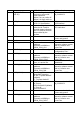
USB 2.0 Specification. USB interface’
8 W_DISABLE#1
(0/3.3V)
I Active low signal used by
the host to turn on/off
radio operation.
When it is Low, radio off.
When it is High, radio on.
Refer to section ‘1.4.5
W_DISABLE#’
9 USB_D- IO USB Data- defined in the
USB 2.0 Specification.
Refer to section ‘1.4.4
USB interface’
10 LED#1 O Active low signal, used to
allow the M.2 card to
provide status indicators
via LED devices that will
be provided by the
system.
Refer to section ‘1.4.6
LED Indication’
11 GND PI Ground Refer to section ‘1.4.2
Power and ground’
12~19
Notch - Notch
20 AUDIO_0 - Don’t need to connect to
platform;
Connect to MDM9xxx
PRIM_PCM_CLK
Reserve for future
extension, please contact
with us if need to use
these Pins
21 CONFIG_0 O Not connect internally.
Refer to section ‘1.4.1
Configuration Pins ’
22 AUDIO_1 - Don’t need to connect to
platform;
Connect to MDM9xxx
PRIM_PCM_SYNC
Reserve for future
extension, please contact
with us if need to use
these Pins
23 WoWWAN (0/1.8V) O WWAN to wake up the
host, It is active low.
Refer to section ‘1.4.7
WoWWAN’
24 AUDIO_2 - Don’t need to connect to
platform;
Connect to MDM9xxx
PRIM_PCM_DIN
Reserve for future
extension, please contact
with us if need to use
these Pins
25 DPR (0/1.8V) I Hardware pin for
BodySAR Detection
H: No TX power backoff
(default)
L: TX power backoff
Refer to ‘1.4.8 DPR’
26 W_Disable2 I GPS disable:
H:Turn on
GPS/GLONASS (default)
L: Turn off
GPS/GLONASS
Refer to section ‘1.4.5
W_DISABLE#’
27 GND PI Ground Refer to section ‘1.4.2
Power and ground’
28 AUDIO_3 - Don’t need to connect to
platform;
Connect to MDM9xxx
PRIM_PCM_DOUT
Reserve for future
extension, please contact
with us if need to use
these Pins