
User's Manual
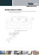
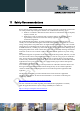
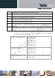

Table Of Contents
- 1 Introduction
- 2 M.2 Overview
- 3 M.2 Module Interface Details
- 3.1 USB 2.0 High-Speed – IPC Interface
- 3.2 (U)SIM Interface
- 3.3 GNSS Interface
- 3.4 System Control Interface
- 3.5 Tunable Antenna Control Interface
- 3.6 In-Device Coexistence Interface
- 3.7 Power Supply Interface
- 3.8 Trace & Debug Interface
- 3.9 Configuration Pins
- 3.10 Reserved Pins
- 3.11 No Connect Pins
- 3.12 Antenna Interface
- 4 Development Tools
- 5 Windows Software Components
- 6 Modem Configuration on Linux Based PC
- 7 Operating Environment
- 8 Power Delivery Requirements
- 9 Other Information
- 10 WWAN Card Type 3042-S3-B
- 11 Safety Recommendations
- 12 Conformity assessment issues
- 13 FCC/IC Regulatory notices
- 14 Document History

xN930 M.2 Hardware User Guide
1VV0301078 Rev.6 – 2013-11-12
14
Document History
Revision
Date
Changes
0
2013-05-20
First issue
1
2013-07-09
• Update setting for Pin 21 on the host interface. This
signal is not connected.
• Updated pin names of pins 1, 21, 69, and 75 in Table 4
and Table 19 to simply reflect HW Configuration use.
• Updated Table 24 to indicate configuration pins 1, 69,
and 75 are tied to GND.
• Rename section 3.6 Coexistence Interface to In-Device
Coexistence Interface. Additional information on the Inter-
device coexistence support was added.
• Updated section 4.1.3 System Trace Tool Section.
• Updated Figure 5 – RF Engine for WW SKU.
• Add further information USB LPM to USB section
• Added information on Seamless Roaming & Wifi Off-
load – SIM_EAP, SIM-AKA under Other Requirements
• Added information on Antenna Design Guidelines
under Other Requirements.
2
2013-07-29
RF bands updated
3
2013-08-26
Updating on RF bands
Updated section 3.5 and 3.4.5
Updated temp range
4
2013-09-09
HN930-DC product was removed from portfolio
5
2013-09-15
Main & Diversity antenna positions have been swapped.
• Updated documentation accordingly, Figure 6 and
Figure 10.
• Updated WWAN M.2 Mechanical drawings, Figure 14
through Figure 17.
• Updated Card_power_ON_OFF description for
UltraBook in Table 9.
• Updated comments in Table 15 regarding the
DPR#/SAR signal.
• Updated SIM DTECTED signal to indicate an external
pull-up.
• Updated Platform Block Diagrams to show DPR#
signal is connected to an EINT pin (not GPIO) on
XGOLD.
• Identified Audio Signals on host interface in Table 4.
Previously these were simply defined as Reserved.
• Updated VBAT requirements in Table 24 and Table
25.
Reproduction forbidden without written authorization from Telit Communications S.p.A. - All Rights Reserved. Page 76 of 77