
User's Manual
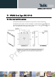
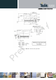
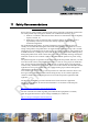
Table Of Contents
- 1 Introduction
- 2 M.2 Overview
- 3 M.2 Module Interface Details
- 3.1 USB 2.0 High-Speed – IPC Interface
- 3.2 (U)SIM Interface
- 3.3 GNSS Interface
- 3.4 System Control Interface
- 3.5 Tunable Antenna Control Interface
- 3.6 In-Device Coexistence Interface
- 3.7 Power Supply Interface
- 3.8 Trace & Debug Interface
- 3.9 Configuration Pins
- 3.10 Reserved Pins
- 3.11 No Connect Pins
- 3.12 Antenna Interface
- 4 Development Tools
- 5 Windows Software Components
- 6 Modem Configuration on Linux Based PC
- 7 Operating Environment
- 8 Power Delivery Requirements
- 9 Other Information
- 10 WWAN Card Type 3042-S3-B
- 11 Safety Recommendations
- 12 Conformity assessment issues
- 13 FCC/IC Regulatory notices
- 14 Document History

xN930 M.2 Hardware User Guide
1VV0301078 Rev.6 – 2013-11-12
10.2
Land Pattern
Figure 16 illustrates a typical land pattern for a top-mount connector with the key removed.
Figure 16 WWAN Card Type 3042 Top-Side Mounting Land Pattern
Reproduction forbidden without written authorization from Telit Communications S.p.A. - All Rights Reserved. Page 66 of 77