
User's Manual
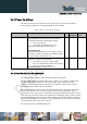


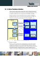

Table Of Contents
- 1 Introduction
- 2 M.2 Overview
- 3 M.2 Module Interface Details
- 3.1 USB 2.0 High-Speed – IPC Interface
- 3.2 (U)SIM Interface
- 3.3 GNSS Interface
- 3.4 System Control Interface
- 3.5 Tunable Antenna Control Interface
- 3.6 In-Device Coexistence Interface
- 3.7 Power Supply Interface
- 3.8 Trace & Debug Interface
- 3.9 Configuration Pins
- 3.10 Reserved Pins
- 3.11 No Connect Pins
- 3.12 Antenna Interface
- 4 Development Tools
- 5 Windows Software Components
- 6 Modem Configuration on Linux Based PC
- 7 Operating Environment
- 8 Power Delivery Requirements
- 9 Other Information
- 10 WWAN Card Type 3042-S3-B
- 11 Safety Recommendations
- 12 Conformity assessment issues
- 13 FCC/IC Regulatory notices
- 14 Document History

xN930 M.2 Hardware User Guide
1VV0301078 Rev.6 – 2013-11-12
Table 14
Wake on WWAN Signal
Signal Name
Detailed Description
Pin
Direction
(WWAN)
Voltage
Level
WAKE_WWAN# Used by M.2 module to wake the
host. Active Low, Open Drain output
23 O (OD) 3.0 V
3.4.5
Dynamic Power Reduction
With the arrival of Tablets and Ultrabook™ platforms where the antenna is in the base of the
unit, there is a significant issue passing Specific Absorption rate (SAR) requirements for
certification.
The WWAN M.2 module has the ability to configure RF TX power levels based on
proximity sensor input from the host.
A WWAN M.2 power control API is available to the host to dynamically reduce RF
transmit power levels of the WWAN module based on proximity sensor input from the
host.
The DPR# (Dynamic Power Reduction) signal is available on the host interface to assist in
meeting regulatory SAR (Specific Absorption Rate) requirements for RF exposure.
Reproduction forbidden without written authorization from Telit Communications S.p.A. - All Rights Reserved. Page 35 of 77