
User Guide


LM960 HW Design Guide
1VV0301485 Rev. 15 Page 62 of 88 2020-08-13
7. RF SECTION
Antenna requirements
The antenna connection is one of the most important aspect in the full product design as it
strongly affects the product overall performance. Hence, please read carefully and follow
the requirements and the guidelines for a proper design.
The LM960/LM960A18 is provided with five RF connectors.
The available connectors are:
Primary RF antenna #0: Tx and Rx path for low bands and middle bands / 4x4
MIMO path of band41.
Primary RF antenna #1: Tx and Rx path for high bands, ultra high bands and
band32 / 4x4 MIMO path of band2(band25) and band4(band66)
Secondary RF antenna #0: Rx Diversity path for low bands, middle bands / 4x4
MIMO path of band41 / GNSS path
Secondary RF antenna #1: Rx Diversity path for high bands, ultra high bands and
band32 / 4x4 MIMO path of band2(band25) and band4(band66)
GNSS antenna: Dedicated GNSS path
The LM960A9-P is provided with four RF connectors.
The available connectors are:
Primary RF antenna #1: Tx and Rx path for ultra high bands
Secondary RF antenna #0: GNSS path
Secondary RF antenna #1: Rx Diversity path for ultra high bands
GNSS antenna: Dedicated GNSS path
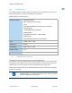
Primary Antenna Requirements
The antenna for the LM960 device must meet the following requirements:
WCDMA / LTE Antenna Requirements
Frequency range
Depending by frequency band(s) provided by the network
operator, the customer shall use the most suitable antenna for
that/those band(s)
The bands supported by the LM960 is provided in Section 2.2,
Product Variants and Frequency Bands.
Impedance 50 Ohm
Input power > 24 dBm average power in WCDMA & LTE