
User Guide


LM960 HW Design Guide
1VV0301485 Rev. 15 Page 57 of 88 2020-08-13
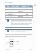
Below table lists the control signals of LM960.
Module Control Signal
PIN Signal I/O Function Type
Comment
20 W_DISABLE_N I
RF disable
(airplane mode)
Open-drain
Internal
VBATT
Pull-up
1
PCIE_
WAKE_N
I/
O
PCIe
wake
-
up
1.8V
42
WAN_LED_N
O
LED control
Open
-
drain
6.6.3.1. W_DISABLE_N
The W_DISABLE_N signal is provided to trigger the LM960 to switch to airplane mode:
Enter into the airplane mode: Low
Normal operating mode: High or Leave the W_DISABLE_N not connected
LM960 contains an internal VBATT(Nominal 3.3V) pull-up resistor on W_DISABLE_N.
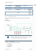
6.6.3.2. WAN_LED_N
The WAN_LED_N signal drives the LED output.
The recommended WAN_LED_N connection is the following:
Recommended WAN_LED_N connection
R1 and VDD determine the brightness of LED and forward current.
When VDD is 3.3V and LED’s forward voltage is 2.0V, it is recommended to choose R1
value between 66 and 250 Ohm.
However, resistor value must be calculated considering the specification of the LED to
use.