User's Guide

LM940 HW Design Guide
1VV0301352 Rev. 2 Page 43 of 68 2017-07-19
6.5.4.1. Using a GPIO Pin as Input
GPIO pins, when used as inputs, can be tied to a digital output of another device and
report its status, provided the device interface levels are compatible with the GPIO 1.8V
CMOS levels.
If a digital output of a device is tied to GPIO input, the pin has interface levels different
than 1.8V CMOS. It can be buffered with an open collector transistor with a 47 kΩ pull-up
resistor to 1.8V.
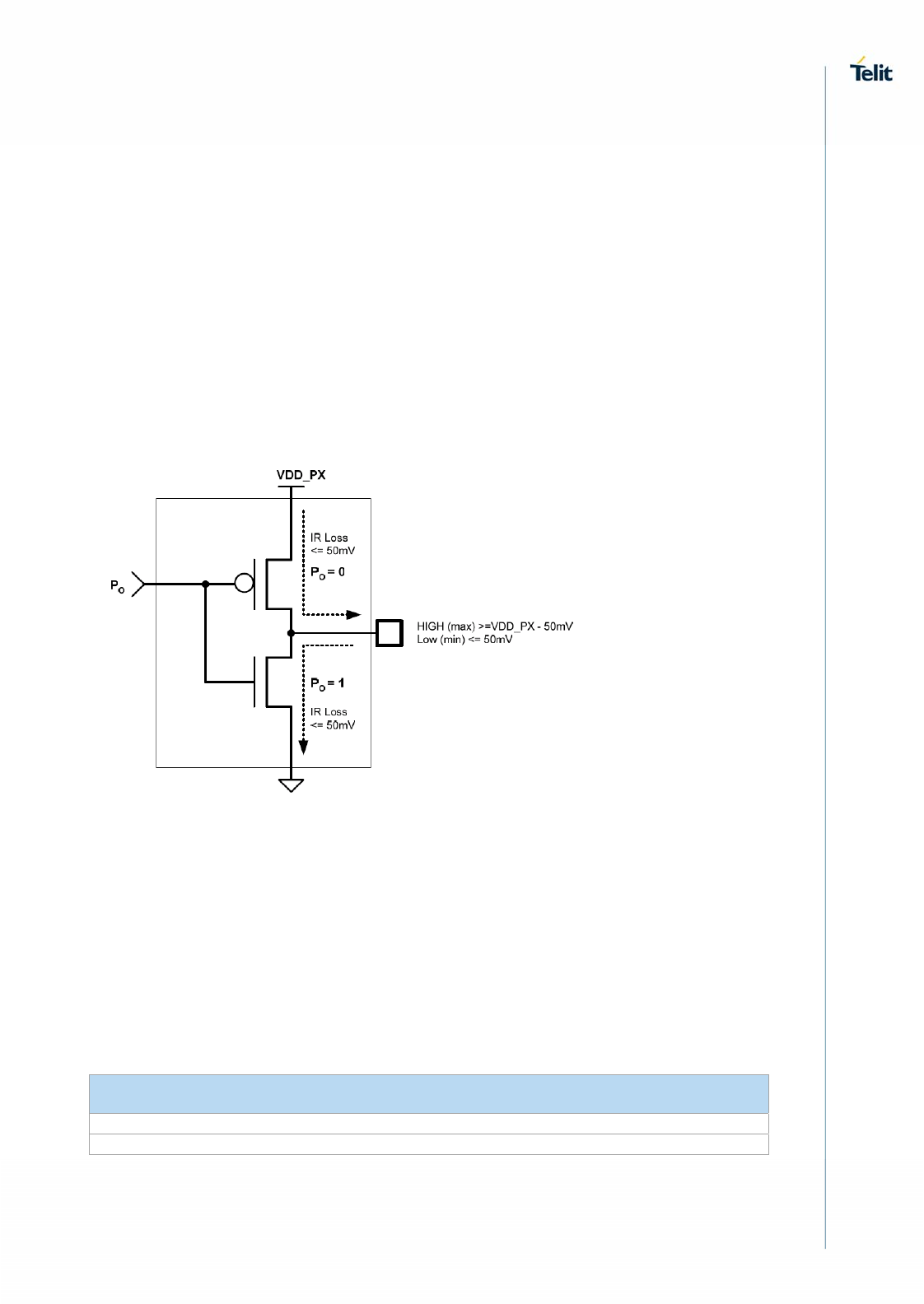
6.5.4.2. Using a GPIO Pin as Output
GPIO pins, when used as outputs, can drive 1.8V CMOS digital devices or compatible
hardware. When set as outputs, the pins have a push-pull output, and therefore the pull-
up resistor can be omitted.
GPIO Output Pin Equivalent Circuit
6.5.5. I2C – Inter-integrated circuit
The LM940 supports an I2C interface on the following pins:
Below table lists the I2C signals of LM940.
Module I2C Signal
PIN Signal I/O Function Type Comment
30 I2C_SCL O I2C Clock CMOS 1.8V
32 I2C_SDA I/O I2C Data CMOS 1.8V
The I2C interface is used for controlling peripherals inside the module (such as codec,
etc.).


