User's Guide

LM940 HW Design Guide
1VV0301352 Rev. 2 Page 38 of 68 2017-07-19
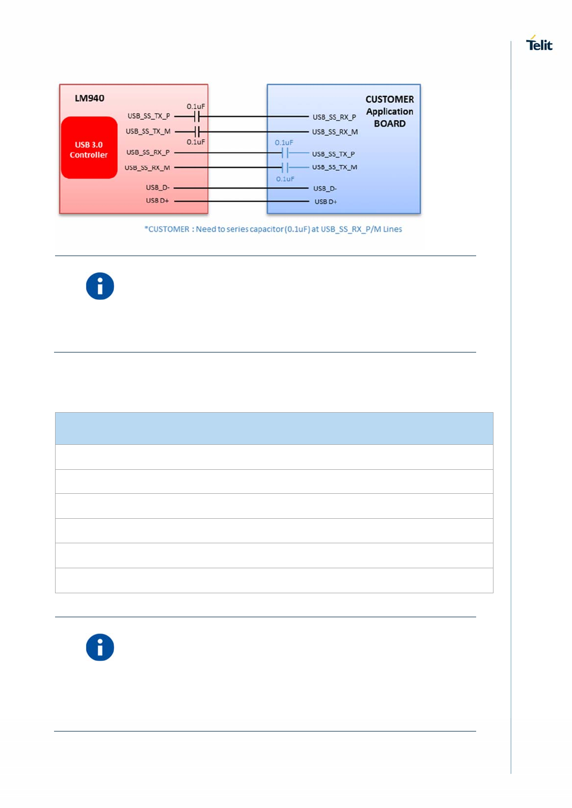
Information – The USB signal traces must be routed carefully.
Minimize trace lengths, number of vias, and capacitive loading. The
impedance value should be as close as possible to 90 Ohms
differential.
Below table lists the USB interface signals.
USB Interface Signals
PIN Signal I/O Function Type Comment
38 USB_D+ I/O USB 2.0 Data Plus Analog
36 USB_D- I/O USB 2.0 Data Minus Analog
33 USB_SS_RX_P I
USB 3.0 super-speed
receive – plus
Analog
31 USB_SS_RX_M I
USB 3.0 super-speed
receive – minus
Analog
25 USB_SS_TX_P O
USB 3.0 super-speed
transmit – plus
Analog
23 USB_SS_TX_M O
USB 3.0 super-speed
transmit – minus
Analog
Information – Even if USB communication is not used, it is still highly
recommended to place an optional USB connector on the application
board.
At least test points of the USB signals are required since the USB
physical communication is needed in the case of SW update.


