
User's Manual
GL865 Hardware User Guide
1vv0300910 Rev.1 – 2011-07-22
Reproduction forbidden without Telit Communications S.p.A. written authorization - All Rights Reserved
page 67 of 79
12.2. ADC Converter
12.2.1. Description
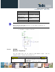
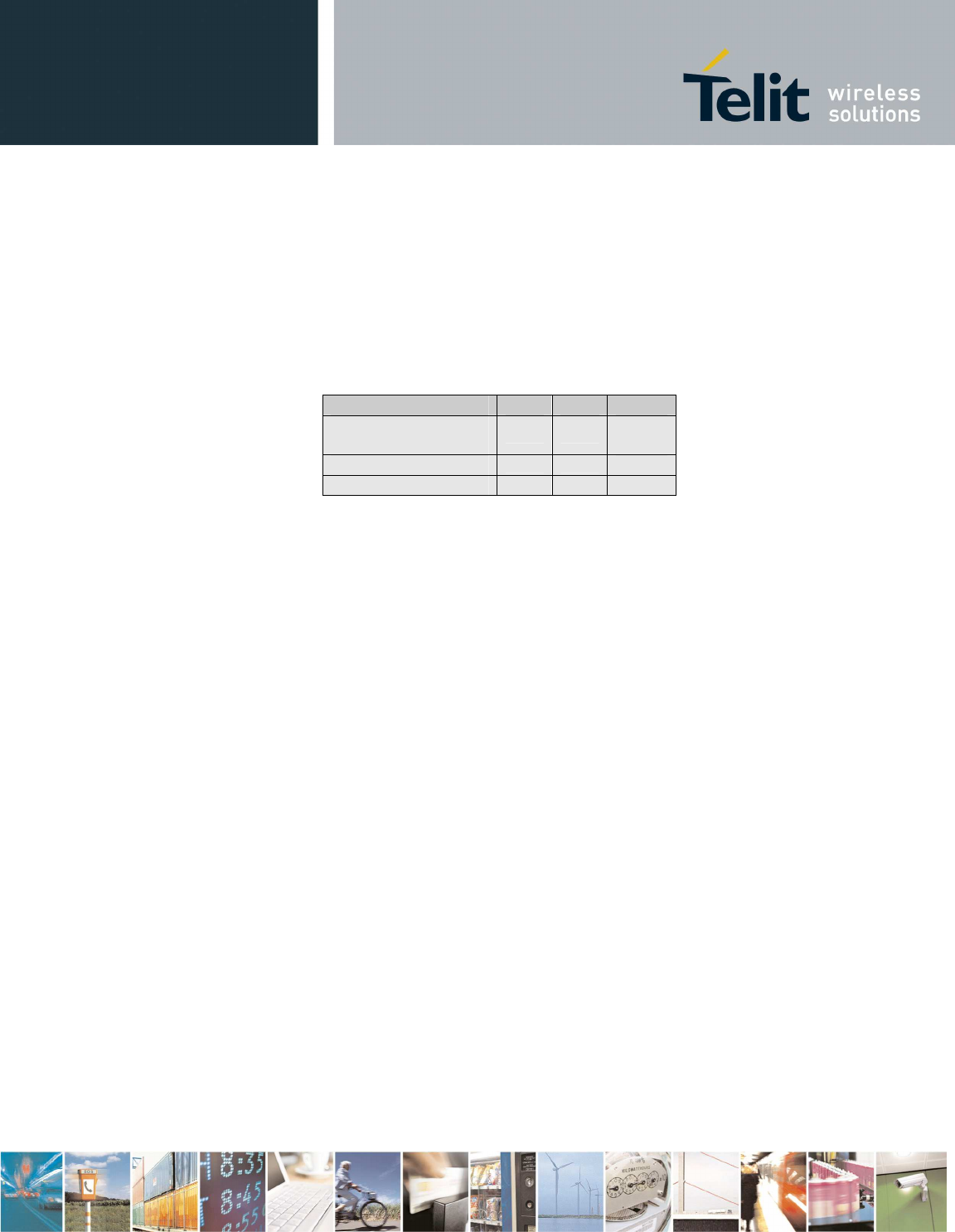
The on board A/D are 11-bit converter. They are able to read a
voltage level in the range of 0÷2 volts applied on the ADC pin
input, store and convert it into 11 bit word.
Min Max Units
Input Voltage
range
0 2
Volt
AD conversion
- 11
bits
Resolution
- < 1
mV
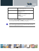
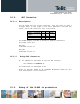
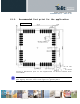
The GL865 module provides 2 Analog to Digital Converters.
The input lines are:
ADC_IN1
available on pin 13
ADC_IN2
available on pin 14
12.2.2. Using ADC Converter
An AT command is available to use the ADC function.
The command is AT#ADC=1,2
The read value is expressed in mV
Refer to SW User Guide or AT Commands Reference Guide for the
full description of this function.
12.3. Debug of the GL865 in production