
User's Manual

GL865 Hardware User Guide
1vv0300910 Rev.1 – 2011-07-22
Reproduction forbidden without Telit Communications S.p.A. written authorization - All Rights Reserved
page 53 of 79
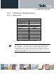
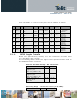
10.1.2. Output Lines
EAR/Line-out Output
Differential line
coupling
Direct connection
(V
DC
=1.3÷1.6V)
Single-ended line
coupling
One EAR terminal
connected via a DC-block
capacitor, the other one
left open
output load resistance ≥ 8 Ω
internal output
resistance
4 Ω (typ.)
signal bandwidth 250÷3400Hz
(@ -3dB with default
filter)
max. differential output
voltage
1120mV
pp
@3.14dBm0 (*)
differential output
voltage
550mV
rms
@0dBm0 (*)
volume increment 2dB per step
volume steps 0..10
(*) in default condition: AT+CLVL=10, AT#HFRECG=0
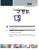
TIP : We suggest driving the load differentially; this kills all
the common mode noises (click and pop, for example), the output
swing will double (+6dB) and the big output coupling capacitor
will be avoided.
However if particular OEM application needs, also a Single Ended
(S.E)
circuitry can be implemented. The OEM circuitry shall be
designed to reduce the common mode noise typically generated by
the return path of the big currents.
In order to get the maximum power output from the device, the
resistance of the tracks has to be negligible in comparison to
the load.
WARNING. When in Single Ended configuration, the unused output
line must be left open: if this constraint is not respected, the
output stage will be damaged.