
User's Manual

GL865 Hardware User Guide
1vv0300910 Rev.1 – 2011-07-22
Reproduction forbidden without Telit Communications S.p.A. written authorization - All Rights Reserved
page 43 of 79
In order to avoid a back powering effect it is recommended to
avoid having any HIGH logic level signal applied to the digital
pins of the GE865 when the module is powered off or during an
ON/OFF transition.
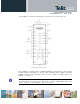
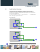
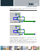
9.2. RS232 level translation
In order to interface the GL865 with a PC com port or a RS232
(EIA/TIA-232) application a level translator is required. This
level translator must:
• invert the electrical signal in both directions;
• change the level from 0/2.8V to +15/-15V .
Actually, the RS232 UART 16450, 16550, 16650 & 16750 chipsets
accept signals with lower levels on the RS232 side (EIA/TIA-562),
allowing a lower voltage-multiplying ratio on the level
translator. Note that the negative signal voltage must be less
than 0V and hence some sort of level translation is always
required.
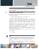
The simplest way to translate the levels and invert the signal
is by using a single chip level translator. There are a
multitude of them, differing in the number of drivers and
receivers and in the levels (be sure to get a true RS232 level
translator not a RS485 or other standards).
By convention the driver is the level translator from the 0-2.8V
UART to the RS232 level. The receiver is the translator from the
RS232 level to 0-2.8V UART.
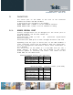
In order to translate the whole set of control lines of the UART
you will need:
• 5 drivers
• 3 receivers
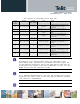
NOTE:
The digital input lines working at 2.8V CMOS have an absolute
maximum input voltage of 3.0V; therefore the level translator IC
shall not be powered by the +3.8V supply of the module. Instead,
it must be powered from a +2.7V / +2.9V (dedicated) power
supply.
This is because in this way the level translator IC outputs on
the module side (i.e. GL865 inputs) will work at +3.8V interface
levels, damaging the module inputs.