
User's Manual
GL865 Hardware User Guide
1vv0300910 Rev.1 – 2011-07-22
Reproduction forbidden without Telit Communications S.p.A. written authorization - All Rights Reserved
page 14 of 79
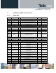
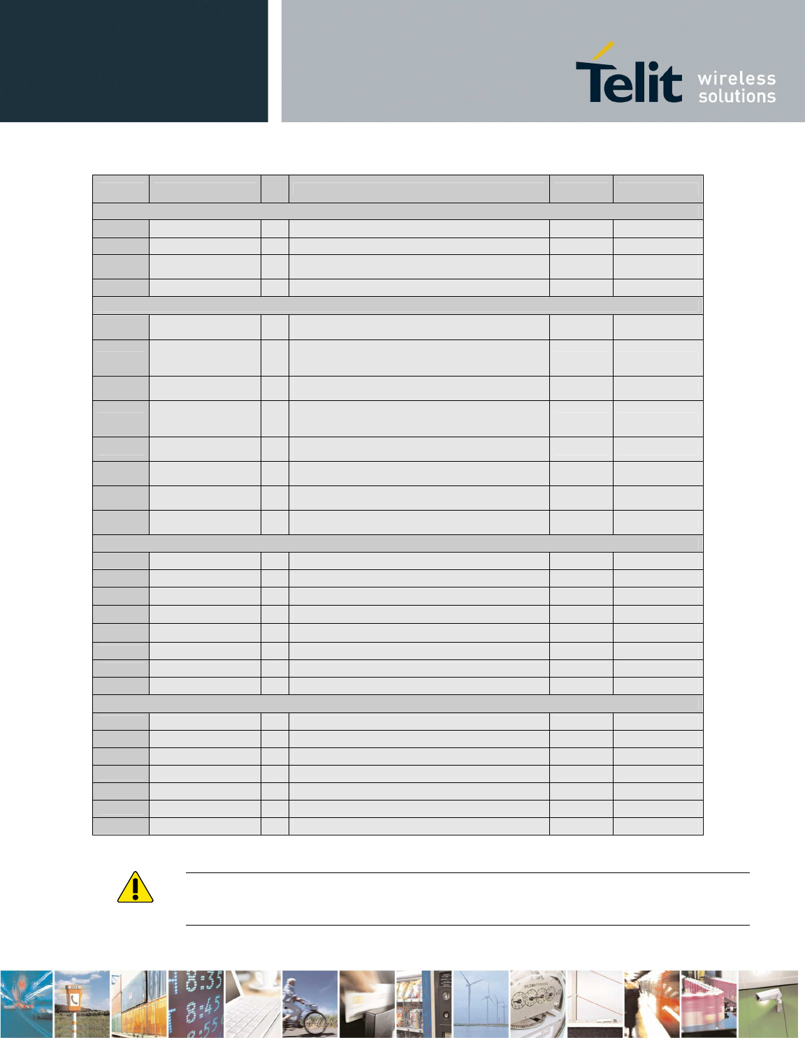
Pad Signal
I/
O
Function Note Type
Miscellaneous Functions
30
VRTC AO
VRTC Backup Power
47
RESET* I Reset input CMOS 1.8V
43
V_AUX / PWRMON O
2.8V stabilized output Imax=100mA
/ Power ON monitor
Power Out
2.8V
34
Antenna O Antenna output – 50 Ω RF
GPIO
42
GPIO_01 /
DVI_WA0
I/
O
GPIO01 Configurable GPIO
/ Digital Audio Interface (WA0)
CMOS 2.8V
41
GPIO_02 / JDR /
DVI_RX
I/
O
GPIO02 Configurable GPIO / Jammer
Detect Report
/ Digital Audio Interface (RX)
CMOS 2.8V
40
GPIO_03 /
DVI_TX
I/
O
GPIO03 Configurable GPIO
/ Digital Audio Interface (TX)
CMOS 2.8V
39
GPIO_04 / TX
Disable /
DVI_CLK
I/
O
GPIO04 Configurable GPIO / TX Disable
input
/ Digital Audio Interface (CLK)
CMOS 2.8V
29
GPIO_05 /
RFTXMON
I/
O
GPIO05 Configurable GPIO
/ Transmitter ON monitor
CMOS 2.8V
28
GPIO_06 / ALARM
I/
O
GPIO06 Configurable GPIO
/ ALARM
CMOS 2.8V
27
GPIO_07 /
BUZZER
I/
O
GPIO07 Configurable GPIO
/ Buzzer
CMOS 2.8V
26
GPIO_08 /
STAT_LED
I/
O
GPIO08 Configurable GPIO
/ STAT LED
CMOS 2.8V
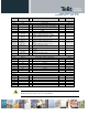
Power Supply
38
VBATT - Main power supply (Baseband) Power
37
VBATT_PA - Main power supply (Radio PA) Power
23
AGND - AF Signal Ground (see audio section) AF Signal
32
GND - Ground Power
33
GND - Ground Power
35
GND - Ground Power
36
GND - Ground Power
46
GND - Ground Power
RESERVED
48
-
16
-
17
-
18
-
19
-
25
-
31
-
WARNING:
Reserved pins must not be connected.