
User's Manual
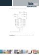
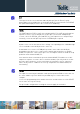
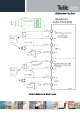
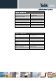
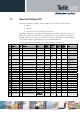
Table Of Contents
- GC864 Hardware User Guide
- APPLICABILITY TABLE
- 1. Introduction
- 2. Overview
- 3. GC864 Mechanical Dimensions
- 4. GC864-QUAD/PY Module Connections
- 5. Hardware Commands
- 6. Power Supply
- 7. Antenna
- 8. Logic Level Specifications
- 9. Serial Ports
- 10. Audio Section Overview
- 11. General Purpose I/O
- 11.1. GPIO Logic Levels
- 11.2. Using a GPIO Pad as INPUT
- 11.3. Using a GPIO Pad as OUTPUT
- 11.4. Using the RF Transmission Control GPIO4
- 11.5. Using the RFTXMON Output GPIO5
- 11.6. Using the Alarm Output GPIO6
- 11.7. Using the Buzzer Output GPIO7
- 11.8. Magnetic Buzzer Concepts
- 11.9. Using the Temperature Monitor Function
- 11.10. Indication of Network Service Availability
- 11.11. RTC Bypass Out
- 11.12. VAUX1 Power Output
- 12. DAC and ADC Section
- 13. Mounting the GC864-QUAD/PY on the Board
- 14. Packing System
- Conformity Assessment Issues

GC864 Hardware User Guide
1vv0300733 Rev.12 – 2009-06-04
“EAR_MT” Output Lines
line coupling
AC single-ended
DC differential
output load resistance
14
internal output resistance
4 (
typical
)
signal bandwidth 150 - 4000 Hz @ -3 dB
max. differential output voltage 1.31 V
rms
(
typical, open circuit
)
differential output voltage
328mV
rms
/16 /
@ -12dBFS
volume increment 2 dB per step
volume steps 10
“EAR_HF” Output Lines
line coupling:
AC single-ended
DC differential
output load resistance :
14
internal output resistance:
4 (>1,7 )
signal bandwidth: 150 - 4000 Hz @ -3 dB
max. differential output
voltage
1.31 V
rms
(
typical, open circuit
)
max. S.E. output voltage 656 mV
rms
(
typical, open circuit
)
volume increment 2 dB per step
volume steps 10
Reproduction forbidden without Telit Communications S.p.A’s. written authorization - All Rights Reserved. Page 49 of 69