APPLICATIONS REVISIONS CHG. NO. DESCRIPTION LTR 10-67-02 11-47-02 04-80-03 12-54-03 03-49-04 NEXT ASSY. USED ON 70-000340 A B C D E F G H DATE APPD RELEASE Manual changed to Rev. B JA Correction of typo JA Manual changed to Rev. D 02-17-03 JA Change TR-825 XLR pinouts, add E88/G9 Antennas 04-29-03 JA 01-05-04 JA 04-22-04 DO 03-16-05 JRC Add CE information Eliminate Customer Service & Limited Warranty in T.O.C.
Telex Operating Instructions RadioCom™ BTR-800, TR-800, TR-825 Professional Wireless Intercom System 0891
Thank you for choosing RadioComTM Telex Communications would like to take this opportunity to thank you for choosing the RadioCom™ BTR-800 Professional Wireless Intercom System. Many of the features in this product are the result of years of development work with many of the features developed from customer feedback. We hope that your experience with this product is a pleasant one and hope to provide you with a continuing line of RadioCom™ products well into the future.
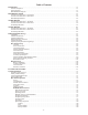
Table of Contents Introduction . . . . . . . . . . . . . . . . . . . . . . . . . . . . . . . . . . . . . . . . . . . . . . . . . . . . . . . . . . . . . . . . . . . . . . . . . . 1-1 General Description . . . . . . . . . . . . . . . . . . . . . . . . . . . . . . . . . . . . . . . . . . . . . . . . . . . . . . . . . . . . . . . . . . . . . . . . . . 1-1 System Features . . . . . . . . . . . . . . . . . . . . . . . . . . . . . . . . . . . . . . . . . . . . . . . . . . . . . . . . . . . . . . . . . . . . . . .
Table of Contents (continued) TR-800 Beltpack Operation . . . . . . . . . . . . . . . . . . . . . . . . . . . . . . . . . . . . . . . . . . . . . . . . . . . . . . . . . . . . . . . . . 7-11 Power/Local Headset Volume. . . . . . . . . . . . . . . . . . . . . . . . . . . . . . . . . . . . . . . . . . . . . . . . . . . . . . . . . . . . . . 7-11 Battery Check . . . . . . . . . . . . . . . . . . . . . . . . . . . . . . . . . . . . . . . . . . . . . . . . . . . . . . . . . . . . . . . . . . . . . . . . . .
Section 1 Introduction General Description System Features The Telex RadioCom™ BTR-800 UHF Synthesized Wireless in ter com sys tems of fer the ul ti mate in re li ab le, high-performance, high-fidelity full-duplex communications. • Frequency-agile base station and beltpacks. No external computer/device required to select frequencies. • Backlit base-station LCD allows the user to easily monitor the beltpack’s status as well as change base-station frequencies.
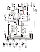
1-2 RECEIVE 4 PORTABLE STATION 4 CONNECT RECEIVE 3 PORTABLE STATION 3 CONNECT RECEIVE 2 PORTABLE STATION 2 CONNECT RECEIVE 1 PORTABLE STATION 1 CONNECT LOGIC LOGIC LOGIC LOGIC 1 OF 5 SELECT 1 OF 5 SELECT 1 OF 5 SELECT 1 OF 5 SELECT ON/OFF LOGIC SA WTA B XLR FEMALE AUXILIARY AUDIO INPUT CHANNEL B MIC GAIN CHANNEL SELECT CHANNEL A WTA A A 4 XLR 2 3 IN TALK VOLUME TALK BTR-800 Block Diagram ON/O.M.
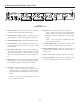
Section 2 BTR-800 Base Station Controls and Connections - Front Panel 1 3 2 RadioComä MENU 4 7 6 5 BTR-800 UP IN 2 3 4 OUT OUT SELECT SET COPY DOWN PORTABLE STATION CONNECT INTERCOM A VOLUME IN OUT MIC GAIN B ON/OFF SELECT INTERCOM B TALK/O.M. A 4 WIRE 4 WIRE 1 ON/O.M. 2 WIRE 2 WIRE IN ClearScan TM 11 9 10 12 8 AUXILIARY SELECT TALK 13 Figure 1 BTR-800 - Front Panel 14 11. Talk/Overmod Light – LED is green when talk button #13 is active.
Controls and Connections - Rear Panel 12 1 BTR-800 FCC ID: B5DM514 CANADA 1321231218A RECEIVE TRANSMIT POWER HIGH ON 2 NORM OFF BASE STATION LINK RELAY CONTACT I/C RTS TELEX CLEARCOM 3 4 INTERCOM B INTERCOM A 2 WIRE 2 WIRE PUSH L O O P T H R U 4 WIRE AUXILIARY AUDIO PUSH L O O P T H R U PUSH 4 WIRE Telex 6 7 TRANSMIT Telex Communications, Inc. INPUT 5 100-240 VAC 50-60 Hz STAGE ANNOUNCE OUTPUT 9 8 OUTPUT POWER 10 11 MADE IN USA Figure 3 BTR-800 - Rear Panel 8.
BTR-800 Specifications Overall RF Frequency Range . . . . . . . . . . . . . . . . . . . . . . 470 - 608 MHz, 614 - 740 MHz in 18 MHz TX and RX bands Power Requirements . . . . . . . . . . . . . . . . . . . . . . . . . . . . . . . . . . . . . . . 100-240 VAC, 50-60 Hz, IEC receptacle Temperature Range . . . . . . . . . . . . . . . . . . . . . . . . . . . . . . . . . . . . . . . . . . . . . . -4° F to 130° F (-20° C to 55° C) Dimensions . . . . . . . . . . . . . . . . . . . . . . . . . . . . . 19.00” W x 1.
2-4 Blank
Section 3 TR-800 Beltpack Controls and Connections - Top Panel 1 5 4 2 Telex WTA OFF 6 R A B BAT/OM TALK 7 SA CHANNEL VOL TALK 3 Figure 4 TR-800 Top Panel 1. On/Off & Volume Control – Turns the beltpack power on and controls headset volume. 5. Bat/Overmod Light (BAT/OM) – Light will flash once when unit is turned on if the battery is good. If the light stays on, battery is low. If the light does not flash, battery is dead.
Controls and Connections - Rear Panel SET MENU 6. Headset Connector – Male XLR connector for Telex units, Female XLR connector for RTS units. A dynamic or electret headset microphone is automatically detected by the beltpack and a bias voltage supplied if needed.
TR-800 Specifications RF Frequency Range . . . . . . . . . . . . . . . . . . . . . . 470 - 608 MHz, 614 - 740 MHz in 18 MHz TX and RX bands Power Requirements. . . . . . . . . . . . . . . . . . . . . . . . . . . . . . . . . . . . . . . . 6 “AA” Cells Alkaline (NiMH optional) Current Draw . . . . . . . . . . . . . . . . . . . . . . . . . . . . . . . . . . . . . . . . . . . . . . . . . . . 140 mA (Push-to-Talk, Talk On) Temperature Range . . . . . . . . . . . . . . . . . . . . . . . . . . . . . . . . . . . .
3-4 Blank
Section 4 TR-825 Beltpack Controls and Connections - Top Panel 1 3 2 1 WTA SA OFF VOL BAT/OM VOL 6 TALK TALK Telex R OFF A 4 6 B 5 4 Figure 7 TR-825 Top Panel 1. On/Off and Volume Control - Turns beltpack power on and controls headset volume for Intercom Channels “A” and “B”. Either knob, “A” or “B”, turns the beltpack on. Both knobs must be off to turn the beltpack off. If only one knob is off, then only that Intercom Channel, “A” or “B” is off for both transmit and receive audio.
Controls and Connections - Rear Panel Telex Units SET MENU (1) Microphone Shield (-) 1 (4) Headphone Low (-) MIC PT PT TX MENU SET 2 3 TALK (2) Microphone Audio (+) 6 8 MIC PT PT TX TALK 4 (1) Microphone Shield (-) 7 9 (2) Microphone Audio (+) 5 (3) Headphone High (+) (5) Headphone Audio B (4) Headphone Audio A (3) Switched Headphone Ground Figure 8 TR-825 Rear Panel/Connector/Antennas (1) Microphone Shield (-) RTS Units (2) Microphone Audio (+) 1.
TR-825 Specifications RF Frequency Range . . . . . . . . . . . . . . . . . . . . . . 470 - 608 MHz, 614 - 740 MHz in 18 MHz TX and RX bands Power Requirements. . . . . . . . . . . . . . . . . . . . . . . . . . . . . . . . . . . . . . . . 6 “AA” Cells Alkaline (NiMH optional) Current Draw . . . . . . . . . . . . . . . . . . . . . . . . . . . . . . . . . . . . . . . . . . . . 190 mA (Push-to-Talk, A and B Talk On) Temperature Range . . . . . . . . . . . . . . . . . . . . . . . . . . . . . . . . . . . . . . .
4-4 Blank
Section 5 Initial Equipment Set-Up Unpacking Unpack your RadioCom™ System. Below are the items that should come with your base station and each belt pack. Quantity BTR-800 Description 1 BTR-800 Base Station 1 Operating Instructions 1 Power Cord 2 Antennas (one Transmit and one Receive) 1 Warranty Card 1 Screwdriver 1 2 terminal plug (for SA Relay) 1 Warning Card 4 Rubber feet Quantity TR-800, TR-825 Contact the shipper or your dealer immediately if anything is damaged or missing.
Antenna Connection The base station is supplied with two (2) antennas. One 1/2-wave antenna for Transmit and one 1/2-wave for Receive. The antennas have TNC male connectors. RadioComä MENU BTR-800 UP ON/O.M. 2 WIRE 2 WIRE VOL IN IN OFF ClearScan 1 2 3 4 OUT OUT SA WTA Te le x A B BAT/OM TALK SELECT The frequency range of the antennas should match the receiver and transmitter of the base station. Match the color code on the antenna with the color code on the base station.
Attempting to operate the wireless intercom system through or around walls, ceilings, metal objects, etc. will reduce system range and performance. Keep the distance between the base station and the beltpacks as short as possible. The greater the distance, the weaker the signal. Make sure the “signal paths” between the base station and beltpacks are unobstructed. You should be able to visibly locate the base station antennas at all times for best performance.
2. Placing the BTR on top of a shelf or equipment rack unobstructed without remoting the antennas is OK. 3. Placing BTRs in a shelf or equipment rack with the antennas mounted on the back of the BTR or the side of the rack is BAD. 1. Placing BTRs in a shelf or equipment rack and using remote antennas is OK. RadioComä MENU BTR-800 UP IN 1 COPY DOWN 2 3 4 PORTABLE STATION CONNECT OUT OUT INTERCOM A Telex VOLUME IN OUT MIC GAIN B ON/OFF SELECT INTERCOM B TALK/O.M.
Base Station Set-up INTERCOM INTERFACE POWER CONNECTION BTR-800 FCC ID: B5DM514 CANADA 1321231218A RECEIVE TRANSMIT POWER HIGH ON NORM OFF BASE STATION LINK INTERCOM B INTERCOM A 2 WIRE RELAY CONTACT I/C RTS TELEX CLEARCOM L O O P T H R U 2 WIRE PUSH 4 WIRE AUXILIARY AUDIO PUSH L O O P T H R U PUSH 100-240 VAC 50-60 Hz STAGE ANNOUNCE 4 WIRE Telex TRANSMIT Telex Communications, Inc.
Internal Transmit Switches Intercom Switch Internal to the BTR-800 are two transmit switches which enable a user to turn on or off the two transmitters individually. See Figure 19 for the location. The top cover of the base station must be removed for access. The switch closest to the front panel controls transmitter 1 (audio channel A). The switch behind that is transmitter 2 (audio channel B). The default switch position is to the left if you are facing the front of the base station.
MODEL PS15 POWER SUPPLY O/N 9000678600 J2 FUSE 0.5A S8/120 VAC J3 NORM 200 DUAL 400 INTERCOM POWER SUPPLY (PS15) RTS SYSTEMS, BURBANK CALIFORNIA MADE IN U.S.A. J1, J2 CONNECT TO TW INTERCOM SYSTEM COMPONENTS REFER TO OPERATION MANUAL OUTPUTS J1 IMPEDANCE SELECT TIP-CH1 RING-CH2 SLEEVE-COM CHN 1 AUDIO COUPLING CM1-CM2 CHN 1 CAUTION FOR CONTINUED PROTECTION AGAINST FIRE REPLACE ONLY WITH SAME TYPE FUSE.
Dual Listen Functionality They will also have the ability to control the level of the mix (-4 dB to -24 dB down from main channel). Removing two surface mount resistors and installing two SPDT switches and two potentiometer enables dual listen. The parts to be installed are shown in Table 1. The two resistors on the board to be removed are in Table 2. The base stations's main audio board has the option of placing additional parts to enable dual listen.
Auxiliary Input/Output The output auxiliary audio is also taken from the intercom B base local headset, beltpack(s), headsets, and any wired intercom connected to the base station. A modification document is available from Telex Communications for those who wish to modify the base station so that auxiliary input audio is heard only locally; base local headset and beltpack(s) headsets.
AUXILIARY INTERFACE BTR-800 FCC ID: B5DM514 CANADA 1321231218A RECEIVE TRANSMIT POWER HIGH ON I/C NORM OFF BASE STATION LINK RTS TELEX CLEARCOM INTERCOM B INTERCOM A 2 WIRE RELAY CONTACT 2 WIRE PUSH L O O P T H R U 4 WIRE AUXILIARY AUDIO PUSH L O O P T H R U PUSH 100-240 VAC 50-60 Hz STAGE ANNOUNCE 4 WIRE Telex TRANSMIT Telex Communications, Inc.
BASE STATION LINK BTR-800 FCC ID: B5DM514 CANADA 1321231218A RECEIVE TRANSMIT POWER HIGH ON NORM OFF INTERCOM B INTERCOM A 2 WIRE BASE STATION LINK I/C RTS TELEX CLEARCOM 2 WIRE PUSH L O O P T H R U RELAY CONTACT AUXILIARY AUDIO PUSH L O O P T H R U 4 WIRE PUSH 100-240 VAC 50-60 Hz STAGE ANNOUNCE 4 WIRE Telex TRANSMIT Telex Communications, Inc.
Beltpack Set-up Battery Installation Ensure that the On/Off volume control knob is turned off. Press down and hold down the battery release latch, slide the battery pack about 1/8 inch back, toward the latch, until it stops. Then lift battery pack out. Replace batteries as follows: 1. Open the battery pack by inserting finger nail and lifting. 2. Pull battery strap to remove low or dead batteries. 3. Load new batteries following the polarity as shown in battery case 4.
MENU SET MICROPHONE GAIN CONTROL MIC PT PT TX TALK TRANSMIT SWITCH HEADSET CONNECTION RECEIVE ANTENNA BATTERY RELEASE LATCH TRANSMIT ANTENNA Figure 30 TR-800 and TR-825 Rear Panel Antenna Connection Headset Connection The beltpack co mes with two de tach able, screw-type, 1/4-wave antennas. To attach the two antennas, screw into the receptacles at the bottom of the beltpack. The color dot on the screw end of the antenna must match the color dot on antenna receptacle.
5-14 Blank
Section 6 Pre-Walk-Thru Checklist Following the instructions fully to this point you have successfully completed the following checklist: r r r Located the base station properly. Connected power to base station. Connected the 1/2-wave antennas to the base station. Checked frequency range of the antennas with the frequency of the base station by correctly matching color codes. r Connected 1/4-wave antenna to the beltpack.
6-2 Blank
Section 7 System Operation Frequency Plan Overview System Quick Start The BTR/TR-8XX has 36 factory defined frequency groups and 12 user-programmable frequency groups. A Group defines the two base station transmit frequencies and thus the two receive frequencies on all the beltpacks. A Channel defines a base station receive frequency and thus a beltpack transmit frequency.
Base Station Operation LOCAL HEADSET PORTABLE STATION CONNECT POWER RadioComä MENU BTR-800 UP IN 1 2 3 4 OUT OUT SELECT SET COPY DOWN PORTABLE STATION CONNECT INTERCOM A VOLUME IN OUT MIC GAIN B ON/OFF SELECT INTERCOM B TALK/O.M. A 4 WIRE 4 WIRE TM ON/O.M.
Display Contrast The LCD’s (Liquid Crystal Display) contrast is set from the factory to a standard level. However it is possible for the user to adjust the contrast if desired. The contrast control is internal to the BTR-800 unit near the front panel. The cover must be removed for access to this control. Please see Figure 31 for the location.
BTR-800 Menu Structure Main Screen Flowchart The following contains the base station menu structure and references the pages in which further detail of that menu may be found. Power-Up Screen - Pg. 7-5 Telex SB10001 C60001 RadioCom TM Operating Screen - Pg. 7-5 Group 25u R1 no tx 2 Ch A 3 Ch B T1 On 4 TA A 2 On [MENU] + [SET] ClearScan Start-up/Search Screen - Pg. 7-9 TM ClearScan [MENU] Group/Channel Select Screen - Pg.
Power-Up Screen • This screen is displayed only on power up, first use default and factory default. • The 1st upper right corner number displays the base’s software revision. The single version number increments for changes in operational software. • The 2nd upper right corner number displays the base’s channel map (frequency plan) version. The single version number increments for changes in the channel map.
Group / Channel Select Group / Channel Select The Group/Channel select screen allows the user to change the group and select from a pre-determined number of channels on each receiver. • Group 14 T1 On T1 2 On Hit [MENU] once to enter the Group / Channel Select Screen from the operating screen. R1 Ch 2 Ch 3 Ch 4 Ch 01 02 03 04 [SET] • Hit [SET] to enter group edit. The group number will start flashing. If [SET] is hit again without hitting the arrows, the display will go to receive 01 channel edit.
Group / Frequency Select Group / Frequency Select The Group/Frequency select screen allows a user to set the group and select from a pre-determined number of frequencies on each receiver. Each frequency displayed on the right half of the screen corresponds to a chan nel num ber in the Group/Channel Screen. Group 15 • • • R1 715.000 2 716.700 T1 568.500 3 719.700 T1 2 569.700 4 721.600 Press [MENU] twice to go to the Group / Frequency Select screen from the operating screen.
Frequency Edit Frequency Edit (User-Programmed Groups Only) (User-Programmed Groups Only) This menu only occurs for user-programmable groups or when copying to a user-programable group. The Frequency Edit screen allows the user to set the group transmit frequencies and receive chan nel frequen cies of a user-programmable group. • Group 25u Freq Edit 554.250 565.350 Press [MENU] three times to go to the frequency select screen from the operating screen. Press [SET] to start the group number flashing.
ClearScan™ ClearScan™ ClearScan™ performs a frequency scan of the factory-defined and any set-up user-programmable groups in order to find the group with the highest number of clear receive channels. After about 20-30 seconds, the group with the highest number of clear receive channels will be displayed. The next best group and so forth may be accessed with the [DOWN] and [UP] arrow buttons. TM • Press and hold [MENU] + [SET] for three seconds to enter ClearScan™.
Special Key Sequences Lockout 1st Use Default • • Press [UP]+[DOWN] for 3 seconds to lock or unlock the base station. Pressing [MENU] will still function to view screens, but [SET] will no longer start any editing. ClearScan™ , First use, Factory default are no longer accessible. The intercom channel A and B front panel 2-wire/4-wire selection is also locked into place.
Beltpack Operation WIRELESS TALK AROUND (WTA) ON/OFF and VOLUME CONTROL Telex A WTA TR-800 OFF BATTERY CHECK R B BAT/OM TALK TALK BUTTON SA TALK AUDIO CHANNEL SELECT BUTTON STAGE ANNOUNCE (SA) MENU SET CHANNEL VOL MIC PT PT MICROPHONE GAIN TX TALK WIRELESS TALK AROUND (WTA) STAGE ANNOUNCE (SA) TR-825 WTA ON/OFF and VOLUME CONTROL ON/OFF and VOLUME CONTROL SA OFF VOL BAT/OM VOL TALK TALK Telex R OFF A B TALK TALK BUTTON BUTTON BATTERY CHECK Figure 32 TR-800 and TR-825 T
TR-800 Menu Structure Beltpack Menu Structure The following contains the main beltpack menu structure and references the pages in which further detail of that menu may be found. All beltpack features and special key sequences can only be done from the group/channel screen. Power-Up Screen - Pg. 7-13 S10001 c60001 Group/Channel Screen - Pg. 7-14 03A GP [MENU] + [SET] ClearScan Search Screen - Pg. 7-18 Clr Scn 01 CH GP [MENU] Transmit Screen - Pg. 7-15 ClearScan Result Screen - Pg. 7-18 TX 704.
TR-800 Menu Structure Power-Up Screens Power-Up Screens • The first screens displayed when the beltpack is powered up are the software and channel map version screens. • The 1st screen displayed indicates the beltpack’s software version number. It is displayed for about one second. • The 2nd screen displayed indicates the beltpack’s channel map (frequency plan) version number. It is displayed for about one second.
TR-800 Menu Structure Group / Channel Screen Group / Channel Screen The Group/Channel screen allows the user to change the group and select from a pre-determined number of transmit channels. 03A • GP The screen displayed after the beltpack power-up screens. 01 CH [SET] • 03A Press [SET] to edit the channel number. The channel number will start flashing. GP 01 CH [UP]/[DOWN] • 03A Use the [UP]/[DOWN] arrow buttons to change the channel number.
TR-800 Menu Structure Transmit Screen Transmit Screen The Transmit screen allows the user to set the beltpack transmit frequency. Factory-defined groups will allow only a set num ber of pre-defined fre quen cies to be se lected. User-programmable groups will allow the user to change the frequency in 25kHz steps. • TX Press [MENU] once from the group/channel screen to arrive at the transmit frequency screen. 704.700 [SET] • TX Press [SET] to edit the frequency. The number will start flashing. 704.
TR-800 Menu Structure Receive 1 Screen Receive 1 Screen The Receive 1 screen allows the user to set the beltpack receive 1 frequency. This corresponds to the base station’s transmit 1 frequency. In factory-defined groups receive 1 is not changeable. User-programable groups will allow the user to change the frequency in 25 KHz steps. R1 • 554.250 Press [MENU] twice from the group/channel screen to arrive at the receive 1 frequency screen.
TR-800 Menu Structure Receive 2 Screen Receive 2 Screen The Receive 2 screen allows the user to set the beltpack receive 2 frequency. This corresponds to the base station’s transmit 2 frequency. In factory-defined groups receive 1 is not changeable. User-programable groups will allow the user to change the frequency in 25 KHz steps. R2 • 565.350 Press [MENU] three times from the group/channel screen to arrive at the receive 2 frequency screen.
TR-800 Menu Structure ClearScan™ ClearScan™ ClearScan performs a frequency scan of the factory-defined and any set-up user-programmable groups in order to find the clearest group. After about 30 seconds, the clearest group is displayed. A group is defined by receive 1 and 2 frequencies. The next best group and so forth may be accessed with the [DOWN] and [UP] arrow buttons. TM • • Press and hold [MENU] + [SET] for three seconds to enter ClearScan .
TR-800 Menu Structure HOLD [SET] AND PRESS [SA] Stage Announce Enable/Disable • Press and hold [SET] then press the [SA] button to show the SA enable/disable screen. The current setting of the feature is displayed on the LCD. SA on CONTINUE TO HOLD [SET] AND PRESS [SA] AGAIN • While continuing to hold [SET] press [SA] again to toggle the display from ON to OFF or back. Release the [SET] button to accept the current displayed setting and return to the Group/Channel screen.
TR-800 Menu Structure Disabling Audio Channel A Audio Channel A or B Disable/Enable HOLD [SET] AND PRESS [CHAN] • Press and hold [SET] then press the [CHAN] button to show the channel enable/disable screen. The current setting of the feature is displayed on the LCD. Ab on CONTINUE TO HOLD [SET] AND PRESS [CHAN] AGAIN • While continuing to hold [SET], press the [CHAN] button again to move to the next option, only channel B on.
TR-800 Menu Structure Special Key Sequences Lockout • Press [UP]+[DOWN] for 3 seconds to lock or unlock the beltpack. The words “Loc on” will be displayed when the feature is activated, “Loc oFF” will be displayed when the beltpack is unlocked. Pressing [MENU] will still function to view screens, but [SET] will no longer start any editing. ClearScan™, First use, Factory default and Feature enable/disable are no longer accessible.
TR-825 Menu Structure Beltpack Menu Structure The following contains the main beltpack menu structure and references the pages in which further detail of that menu may be found. All beltpack features and special key sequences can only be done from the group/channel screen. Power-Up Screen - Pg. 7-23 S30001 c60001 Group/Channel Screen - Pg. 7-24 03A GP [MENU] + [SET] ClearScan Search Screen - Pg. 7-29 Clr Scn 01 CH GP [MENU] Transmit Screen - Pg. 7-25 ClearScan Result Screen - Pg. 7-29 TX 704.
TR-825 Menu Structure Power-Up Screens Power-Up Screens • The first screens displayed when the beltpack is powered up are the software and channel map version screens. • The 1st screen displayed indicates the beltpack’s software version number. It is displayed for about one second. S30001 • The 2nd screen displayed indicates the beltpack’s channel map (frequency plan) version number. It is displayed for about one second. The operating screen is then displayed.
TR-825 Menu Structure Group / Channel Screen Group / Channel Screen The Group/Channel screen allows the user to change the group and select from a pre-determined number of transmit channels. • 03A The screen displayed af ter the beltpack powered-up screens. GP 01 CH [SET] • Press [SET] to edit the channel number. The channel number will start flashing. 03A GP 01 CH [UP]/[DOWN] • 03A Use the [UP]/[DOWN] arrow buttons to change the channel number.
TR-825 Menu Structure Transmit Screen Transmit Screen The Transmit screen allows the user to set the beltpack transmit frequency. Factory-defined groups will allow only a set num ber of pre-defined fre quen cies to be se lected. User-programmable groups will allow the user to change the frequency in 25kHz steps. TX • 704.700 Press [MENU] once from the group/channel screen to arrive at the transmit frequency screen. [SET] • Press [SET] to edit the frequency. The number will start flashing.
TR-825 Menu Structure Receive 1 Screen Receive 1 Screen The Receive 1 screen allows the user to set the beltpack receiver 1 frequency. This corresponds to the base station’s transmit 1 frequency. In factory-defined groups receiver 1 is not changeable. User-programmable groups will allow the user to change the frequency in 25kHz steps. • R1 Press [MENU] twice from the group/channel screen to arrive at the receive 1 frequency screen. 554.
TR-825 Menu Structure Receive 2 Screen Receive 2 Screen The Receive 2 screen allows the user to set the beltpack receive 2 frequency. This corresponds to the base station’s transmit 2 frequency. In factory-defined groups receiver 2 is not changeable. User-programable groups will allow the user to change the frequency in 25kHz steps. • R2 Press [MENU] three times from the group/channel screen to arrive at the receive 2 frequency screen. 565.
TR-825 Menu Structure Audio Output Audio Output The Audio Output screen allows the user to set the audio output to Mono (Add) or Stereo (SEP). This option only applies to beltpacks with 5 pin headset connectors. Single sided 5-pin headsets will only receive A or B Audio depending on how the headset is wired. Single sided 5-pin headsets must set the audio output to "Ab SEP". The audio output option setting does nothing with a 4 pin headset connector.
TR-825 Menu Structure ClearScan TM ClearScan™ ClearScanTM performs a frequency scan of the factory-defined and any set-up user-programmable groups in order to find the clearest group. After about 30 seconds, the clearest group is displayed. A group is defined by receive 1 and 2 frequencies. The next best group and so forth may be accessed with the [DOWN] and [UP] arrow buttons. • Press and hold [MENU] + [SET] for three seconds to enter ClearScanTM.
TR-825 Menu Structure Stage Announce Enable/Disable • SA Press and hold [SET] then press the [SA] button to show the SA enable/disable screen. The current setting of the feature is displayed on the LCD display. on CONTINUE TO HOLD [SET] AND PRESS [SA] • While continuing to hold [SET] press [SA] again to toggle the display from ON to OFF or back. Release the [SET] button to accept the current displayed setting and return to the Group/Channel screen.
TR-825 Menu Structure Wireless Talk Around • Press and hold [SET] then press the [WTA] button to show the WTA menu screen. The current setting of the feature is displayed on the LCD display. The first screen to the right is currently set to a default of “A” channel, nonlatching. HOLD [SET] AND PRESS [WTA] tA A CONTINUE TO HOLD [SET] AND PRESS [WTA] AGAIN • While continuing to hold [SET] press [WTA] again to go to the next se lection; Talk Around = “B” chan nel, non-latching.
TR-825 Menu Structure Audio Channel A Options Audio Channel A Options HOLD [SET] AND PRESS [A] • Press and hold [SET] then hit the [A] button to show the channel “A” menu screen. The current setting of the button is displayed on the LCD dis play; Chan nel “A” “Talk-Latching Off”. A on CONTINUE TO HOLD [SET] AND PRESS [A] AGAIN • A While continuing to hold [SET], press the [A] button again to move to the next option; Channel “A” Talk Latching On.
TR-825 Menu Structure Audio Channel B Options Audio Channel B Options HOLD [SET] AND PRESS [B] • Press and hold [SET] then hit the [B] button to show the channel “B” menu screen. The current setting of the button is displayed on the LCD dis play; Chan nel “B” Talk-Latching Off. b on CONTINUE TO HOLD [SET] AND PRESS [B] AGAIN • While continuing to hold [SET], press the [B] button again to move to the next op tion; Chan nel “B” Talk-Latching On.
TR-825 Menu Structure Special Key Sequences Lockout • Press [UP]+[DOWN] for 3 seconds to lock or unlock the beltpack. The words “Loc on” will be displayed when the feature is activated, “Loc oFF” will be displayed when the beltpack is unlocked. Pressing [MENU] will still function to view screens, but [SET] will no longer start any editing. ClearScan™, First use, Factory default, and Feature enable/disable are no longer accessible.
Section 8 System Walk-Thru Now that you have successfully “set-up” your Telex Wireless Intercom System and turned on any auxiliary equipment, you are ready to test the overall performance by “Walking” the Telex system through the areas in which you will be using it.
8-2 Blank
Section 9 Troubleshooting Reread the sections of this manual to make sure you have completed system set-up properly. If you are unable to solve the problem, contact the dealer from whom you purchased the system for assistance. PROBLEM SOLUTION DISTORTION - System’s audio quality seems distorted at medium to high input levels. Reduce microphone gain by adjusting microphone gain control. HISS - System seems to produce a “hiss” which is undesirable. Check the gain setting on all beltpacks and the base.
9-2 Blank
Section 10 Tech Tips Frequency Interaction Unfortunately, radio frequency (RF) channels cannot be randomly selected for use in radio devices. They must be selected to avoid known frequencies in use, FCC restrictions on the location of devices, and even interference between your own RF devices. The factory defined frequencies (Groups 01A-24) selected by Telex for this RadioCom™ system are chosen to minimize possible interference.
10-2 Blank
Section 11 Battery Information Improper battery selection, use, installation and care are the cause of numerous wireless system failures. Battery Life: TR-800 Alkaline, 12-14 Hours Nickel Metal Hydride, 9-11 Hours Alka line Batteries: Alkaline batteries such as Mallory’s DURACELL® or Eveready’s ENERGIZER® provide the most reliable operation in wireless transceivers. TR-825 Alkaline, 9-11 Hours Nickel Metal Hydride, 7-9 Hours The use of low cost carbon-zinc batteries is NOT recommended.
11-2 Blank
Section 12 Intercom Systems Specifications COMMON RTS Input Impedance:...............................................................200W Output Level:.............................................0.775 Vrms nominal Bridging Impedance:.......................................................>10kW Call Signaling: Send: ...................................20kHz ±100 Hz, 240 mVrms Receive: .............................20kHz ±800 Hz, 100 mVrms AUDIO 1 PLUS POWER 1 2 3 AUDIO 2 MALE Power Voltage: ...........
12-2 Blank
Section 13 Accessories and Replacement Parts ALP-600 450-900 MHz Bi-Directional Log Periodic Antenna Includes mounting hardware and 10 feet (3 meters) of coaxial cable with TNC Connectors P N. 878896 Telex AB-2 MICROPHONE STAND MOUNTING Bracket for 1/2 wave Antenna with 10 ft. of coaxPN 71138000 BTR Power Cords Telex ALP-450 450-900 MHz Log Periodic Antenna Includes mounting hardware and 10 feet (3 meters) coaxial cable with TNC connectors ALP-450 North America ......................................
13-2 Blank
Section 14 Software License End-User License Agreement for Telex® Software IMPORTANT - Please red this document carefully before using this product. THIS DOCUMENT STATES THE TERMS AND CONDITIONS UPON WHICH TELEX COMMUNICATIONS, INC. (the “COMPANY”) OFFERS TO LICENSE THE INSTALLED SOFTWARE OR PROGRAM (the “SOFTWARE”) FOR USE WITH THE PRODUCT IN WHICH IT WAS INSTALLED. YOU ARE AGREEING TO BECOME BOUND BY THE TERMS OF THIS AGREEMENT.
14-2 Blank
Section 15 Certification Information FCC LICENSING The Telex BTR-800, TR-800, and the TR-825 Transmitter/Receiver are Type Accepted under United States Federal Communications Commission Part 74. Licensing of Telex equipment is the User’s responsibility and licensibility depends on the user’s classification, users application, and frequency selected. Telex strongly urges the user to contact the appropriate telecommunications authority for any desired clarification.
EU DECLARATION OF CONFORMITY We of : Telex Communications, Inc. 8601 East Cornhusker Highway Lincoln, NE 68507-9702, USA Declare under our sole responsibility that all essential radio test suites have been carried out and that the: Model: BTR-800 Description: Wireless Intercom Base Station Model: TR-800 Description: Wireless Intercom Beltpack Complies with all essential requirements of the R&TTE Directive 1999/5/EC. Conformity is declared against: Radio standards: EMC standards: EN 300 454-2 v1.
TELEX COMMUNICATIONS, INC. • 12000 Portland Ave. South, Burnsville, MN 55337. PN 803257-1 Rev. H MARCH 2005 Made in U.S.A.