Telex Operating Instructions BTR-300 RadioComä Portable Transmit On Ext Intercom Aux Audio Power 1 2 4 3 Headset Controls Portable Station Connect Volume Headset RadioComä TR-300 PROFESSIONAL WIRELESS INTERCOM SYSTEM TR-300, BTR-300 R Talk Gain Push Twice to Latch O/M
TABLE OF CONTENTS INTRODUCTION . . . . . . . . . . . . . . . . . . . . . . . . . . . . . . . . . . . . . . . . . . . . . . . . . . . . . . . . . . . 1 GENERAL DESCRIPTION . . . . . . . . . . . . . . . . . . . . . . . . . . . . . . . . . . . . . . . . . . . . . . . . . . 1 BTR-300 BASE STATION TRANSCEIVER . . . . . . . . . . . . . . . . . . . . . . . . . . . . . . . . . . . . . 3 SPECIFICATIONS . . . . . . . . . . . . . . . . . . . . . . . . . . . . . . . . . . . . . . . . . . . . . . . . . . . . .
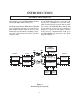
INTRODUCTION GENERAL DESCRIPTION This manual covers the BTR-300 Base Station and the TR-300 Portable Transceiver. At the BTR-300 operator’s command, the remotes may communicate with each other, with a wired intercom system or with an auxiliary system. The BTR-300 Base Station with its one transmit and four receive channels is designed to operate in full duplex (simultaneous two-way communications) with up to four TR-300 Belt Pack transceivers. See block diagram in Figure 1.
The system operates on selected frequencies within the 150-216 MHz band. The TR-300 Transceiver operates in the continuous transmit mode with the audio activated by a switch. As many as four TR-300 belt-pack transceivers can operate in a fully duplex network with one RadioCom Model BTR-300 Base Station. The BTR-300 system is fully compatible with a number of other wired intercom manufacturers units. See the BTR-300 Setup Section for additional information.
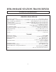
BTR-300 BASE STATION TRANSCEIVER TECHNICAL INFORMATION SPECIFICATIONS BTR-300 Input Power (minimum) ....................................................................................12V AC/DC at 360 mA Intercom Output ........330 mV (Low) or 1 V (Hi) RMS into 300 ohm load typical (at rated deviation) Intercom Input (Gain Minimum) .........................................300 mV RMS typical (for rated deviation) Auxiliary Output.............................................
SPECIFICATIONS BTR-300 (Cont.) Receive RF Frequency Range .......................................................................................................150-216 MHz RF Frequency Stability................................................................................Crystal Controlled, 0.005% Type ...........................................................................................Dual conversion superheterodyne, FM RF Sensitivity ...............................................................
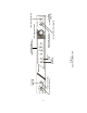
CONTROLS and CONNECTIONS FRONT PANEL (Refer to Figure 3) Mic On-Push-to-Talk/Lock-to-Talk Switch: Enables the local headset microphone audio function. Power ON/OFF Switch: Push this switch once to turn power ON; push it again to turn the power OFF. NOTE: DOES NOT control base station RF transmit. Power ON Indicator: The Power ON light is illuminated when the Power ON/OFF Switch is pushed in the ON Position. Local Push-to-Talk Indicator: Will be illuminated whenever the talk function is on.
Headset Microphone Select Switch: This switch allows the user to select either an Electret or Dynamic microphone. External Intercom Switch, Level Control, and indicator: This switch enables the wired intercom interface when “IN”, and disables it when “OUT”. For RTS intercoms, the “IN” position is channel 1 and the “OUT” position is channel 2. A screwdriver adjustable control is provided to control the input level of the wired intercom.
-7- LOCAL HEADSET CONNECTOR POWER ON-OFF SWITCH Headset Power POWER ON INDICATOR Aux Audio EXTERNAL INTERCOM AUXILIARY AUDIO Ext Intercom 1 2 3 Portable Transmit On 4 Headset Controls LOCAL MIC OVERMODULATION INDICATOR Talk Gain Push Twice to Latch LOCAL PUSH-TO-TALK INDICATOR Volume BTR-300 O/M LOCAL MIC GAIN CONTROL LOCAL HEADSET VOLUME MIC ON PUSH-TO-TALK/ LOCK-TO-TALK SWITCH Portable Station Connect Figure 3 Front Panel BTR-300 RadioComä PORTABLE ENABLE SWITCHES AND INDICATORS
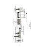
-8- Auxiliary Audio Output ANTENNA COLOR DOT Transmit Antenna TRANSMIT ANTENNA CONNECTOR Dyn Cont Off Remote Transmit BTR-300 Intercom Loop Thru MADE IN U.S.A. Telex Communications Inc. Intercom Loop-Thru ANTENNA COLOR DOT POWER JACK AC/DC 12V 700 mA Power Receive Antenna RECEIVE ANTENNA CONNECTOR MIN.
TR-300 BELT-PACK TRANSCEIVER TECHNICAL INFORMATION SPECIFICATIONS TR-300 Overall Power Requirements ..............................................................6 AA cells (Alkaline, NEDA, MN 1500) Nickel-metal hydride optional Current Drain....................................................................................................................typical 82 mA Temperature Range ................................................................................-4°F to 130°F (-20°C to 55°C) Dimensions..
FEATURES · Lig h twei ght , self-contained. s m al l s i ze and is · 2 separate antennas, one for transmit, the other for receive. · Push-to-Talk with Lock-to-Talk feature switch for the TR-300 and Push-to-Transmit with Lock-to-Transmit feature for the TR-300P. CONTROLS AND CONNECTIONS EXTERNAL CONTROLS (Refer to Figure 6) Volume OFF/ON Control: This thumbwheel control serves as both an off/on switch and as a volume control.
LOW BATTERY / OVERMODULATION INDICATOR LIGHT TALK INDICATOR LIGHT PUSH-TO-TALK/ LOCK-TO-TALK SWITCH talk Bat/ talk ovmod BELT CLIP VOLUME OFF/ON CONTROL HEADSET CONNECTOR BATTERY CHARGE JACK TRANSMIT ANTENNA Figure 6 External Controls, TR-300 -11- RECEIVE ANTENNA
DYNAMIC / ELECTRET SWITCH FCC ID: B5DMXXX S/N: ACCESS TO MICROPHONE GAIN CONTROL CANADA IIIIIIIIIII MIC D E BATTERY COMPARTMENT Figure 7 Internal controls, TR-300 INTERNAL CONTROLS (Refer to Figure 7) Microphone Gain Control: Screwdriver adjustable by removing belt clip and prying out the small rubber plug to the right of the screw boss. Dynamic/Electret Switch: This switch allows selection of “D” when using a Dynamic Microphone or “E” when using and Electret Microphone.
EQUIPMENT SET-UP BTR-300 SET-UP UNPACKING Unpack your BTR-300 and TR-300 System. If there are any damages or shortages, refer to the “Warranty Service Information” section in this manual. INTERNAL INTERCOM SWITCHES The BTR-300 has internal switches that allow it to accommodate intercom systems other than what it was set to interface with when manufactured. Product No. 71276XXXX is set for Telex Audio Com and similar systems. Product No. 71280XXXX is set for RTS 2 wire and similar systems.
Internal Switch Settings Auxiliary Audio Out Pin 1 Pin 2 Pin 3 Auxiliary Audio Input Pin1 Intercom Loop Thru (both jacks) Pin 2 Pin 3 Pin 1 Pin 2 Pin 3 Telex Audio Com Ground 600 ohm Balanced 600 ohm Balanced Ground 2.2K ohm Balanced 2.2K ohm Balanced Ground Balanced Balanced RTS 2 wire Ground 600 ohm Balanced 600 ohm Balanced Ground 2.2K ohm Balanced 2.2K ohm Balanced Ground Channel 1 Channel 2 Clearcom Ground 600 ohm Balanced 600 ohm Balanced Ground 2.2K ohm Balanced 2.
RACK MOUNTING To rack mount the BTR-300 base transceiver do the following: Remove the front two #6-32 x 3/8” screws on each side of the transceiver as shown in Figure 9. Place the rack mount brackets (supplied) on either side of the unit and insert three #6-32 x 3/8” screws for each bracket. Tighten the screws securely. Insert the BTR-300 into your 19” rack enclosure and insert four (4) #10-32 x 3/8” Phillips pan head screws (supplied) in each corner of the rack mount brackets and secure to your enclosure.
ANTENNA INFORMATION ANTENNA CONNECTIONS The BTR-300 is supplied with two (2) antennas. One 5/8-wave antenna for Transmit and one 5/8-wave antenna for Transmit and one 5/8-wave for Receive. Assemble the 5/8-wave antenna by screwing the two sections together as shown in Figure 10. Both sections of the BTR-300 5/8-wave antennas must be used. Leaving off the top section will result in reduced range.
You will also need to remote the transmit antenna in the same manner. Connect a coax cable assembly to the transmit antenna receptacle. Mount the 5/8-wave antenna by attaching it to a bracket (not supplied). Remoting Antennas: It will be necessary to remote both the transmit and receive antennas on the BTR-300 when it is rack mounted. Connect the coax cable assembly (not supplied), to the receive antenna receptacle and mount the 5/8-wave antenna.
ANTENNA POLARIZATION The Telex Wireless Intercom System is “Vertically Polarized”. This means both the transmitting and receiving antennas should operate in the vertical position.
Attempting to operate the wireless intercom system through or around walls, ceilings, metal objects, etc. will reduce system range and performance. DO NOT - mount the BTR-300 5/8-wave antennas next to metal such as beams, walls with metal studs, equipment racks, etc. This also applies to the antennas when assembled directly to the BTR-300. This will “detune” the receiving antenna which can result in noise or loss of RF signal at the BTR-300. See Figure 17.
LOCAL HEADSET CONNECTION Insert the headset/microphone into the 4 pin XLR connector on the front panel. See the microphone connection diagram (Figure 2) if other than a Telex Headset is used. HEADSET MICROPHONE SELECT SWITCH If the headset you are using has an Electret microphone, the local microphone select switch must be in the “ELT” position (Electret). This switch is located on the rear panel. A +5 volt bias is available at the microphone plug for electret use.
Connect the intercom cable to the back of the BTR-300. There are two intercom connections on the back of the unit, one being a male connector, the other a female connector, connected in parallel with each other. Either works as an input or output. INTERCONNECTION to a HARD-WIRED INTERCOM SYSTEM The RADIOCOM wireless system can be integrated into Telex intercom systems and most existing wired intercom systems including RTS and Clearcom.
Transmit Antenna PUSH Telex Communications Inc. Auxiliary Audio Input BTR-300 Auxiliary Audio Output Dyn Elt PUSH Intercom Loop Thru Receive Antenna Intercom Loop-Thru Transmit Headset Mic Cont Off Power Volume Remote MADE IN U.S.A. Speaker 8 AC/DC 12V 700 mA DUMMY LOAD (IF USED) Transmit Antenna PUSH Auxiliary Audio Output Telex Communications Inc.
TR-300 SET-UP HEADSET CONNECTION BATTERY INSTALLATION Inset the headset/microphone into the connector on the bottom of the unit. See the connection diagram (Figure 5) if headsets other than Telex are used. Insure that the OFF/ON Volume control knob is turned OFF. Access the battery compartment by removing the belt clip on the back of the unit. Release the 1/4 turn fastener located on the back of the belt clip and remove belt clip/cover. ä Remove the battery holder from the box.
PRE-WALK-THRU CHECKLIST Following the instructions fully to this point, you have successfully completed the following checklist: Set transmit switch on BTR-300. Connected headsets to BTR-300 and all TR-300’s Set (if necessary) the internal intercom switches to correspond with the wired intercom. Connected the BTR-300 to any auxiliary audio, intercom or external speaker. Located the BTR-300 transceiver properly. Connected power to BTR-300 transceiver.
SYSTEM OPERATION BTR-300 OPERATION POWER If you have followed the instructions until this point, you should now be ready to turn both the TR-300 and the BTR-300 “ON”. Place the power switch on the BTR-300 in the “ON” position. The red power on indicator light should illuminate. PUSH TO SWITCH TALK/LOCK-TO-TALK To enable the talk function on the BTR-300, press and hold down on the talk button and begin talking. Releasing the talk button will discontinue the microphone audio.
TR-300 OPERATION POWER PUSH TO TALK/PUSH TO TRANSMIT You should now be ready to turn the TR-300 “ON”. Rotate the OFF/ON Volume Control Switch on the TR-300 clockwise to turn the unit on. To enable the talk function on the Model TR-300 press and hold down on the talk button and begin talking. Releasing the talk button will discontinue the microphone audio. For continuous talk, quickly press the talk button twice. This locks on the talk function. To release the talk function press the talk button once.
ENABLING AUDIO PORTABLE TRANSCEIVERS Select the TR-300 portables that will be used with the BTR-300. Push in the portable enable switches that correspond to the TR-300 remotes that you will be using. The numbers of the portable stations (1, 2, 3, and 4), are the last digit of the product number on the back of the TR-300. The Portable Transmit On light will illuminate when the remote on that frequency is turned on.
SETTING SYSTEM GAIN LEVELS ADJUSTING GAIN BTR-300 BASE STATION The gain may need to be adjusted for various audio conditions. The overmodulation light will indicate when the gain is too high. If the light is illuminated when you are talking, the gain is too high and will need to be decreased. If the light does not flash at all, and the audio is low, the gain may need to be increased. An occasional flash of the overmodulation indicator is fine.
INTERCOM GAIN AUXILIARY GAIN If the audio volume at the intercom input is too high, the light will be illuminated when the person on the intercom is talking. Decrease the gain until the light does not illuminate while talking at normal volume. Occasional flashing of the light is allowable. See Figure 36. If the audio volume at the auxiliary input, is too high, the Aux light will be illuminated when the person on the auxiliary is talking.
TROUBLESHOOTING Reread the sections of this manual to make sure you have completed system set-up properly. If you are unable to solve the problem, contract the dealer from whom you purchased the system for assistance. PROBLEM SOLUTION DISTORTION - System’s audio quality seems distorted at medium to high input levels. Reduce microphone gain by adjusting microphone gain control. HISS - System seems to produce a “hiss” which is undesirable. Check the gain setting on all beltpacks and the base.
BATTERY INFORMATION GENERAL Improper battery selection, use, installation, and care are the cause of numerous wireless system failures. Alkaline Batteries: Alkaline batteries such as Mallory’s DURACELL or Everready’s ENERGIZER provide the most reliable operation in wireless transceivers. The use of low cost carbon-zinc batteries is NOT recommended. BC-300NM1 BATTERY CHARGER NOTE: The BC-300NM1 is not supplied with the TR-300. See the “Accessory” section for ordering information.
BC-300NM2 BATTERY CHARGER NOTE: The BC-300NM2 is not supplied with the TR-300. See “Accessory” Section for ordering information. Full charge of the battery pack is obtained after 12 to 14 hours. A full charge will last 15 -17 hours with nickel-metal hydride batteries. Remove the battery holder from the TR-300. Extensive over-charging may damage or destroy the batteries. Please ensure the charging time does not exceed 24 hours. CAUTION DO NOT ATTEMPT TO CHARGE ANY ALKALINE BATTERIES WITH THIS CHARGER.
ACCESSORIES AB-300 Microphone Stand/Surface Mount Bracket - for 5/8-wave antenna. Includes necessary hardware. Order No. 63906-100 BC-300NM1 Battery Charger Order No. 70741-001 Includes 6 nickel-metal hydride batteries and 1 carrier. Charges a TR-300 without removing the battery pack. 25’ Coax Cable Order No. 63901-000 BC-300NM2 Battery Charger Order No. 70741-002 Includes 6 nickel-metal hydride batteries and 1 carrier. Charges 1 set of batteries outside of the TR-300. 4’ Coax Cable Order No.
CUSTOMER SERVICE INFORMATION If your receiver or transmitter should need servicing under the warranty, please contact: Customer Service Department TELEX COMMUNICATIONS, INC. 8601 East Cornhusker Highway, P.O. Box 5579, Lincoln, Nebraska 68505-5579 U.S.A. Phone: (402) 467-5321 or 465-7021 All claims of defect or shortage should be sent to the above address. When returning items for service, you must provide date and proof of purchase, such as a copy of the sales receipt, to establish warranty.
FCC INFORMATION The Telex Models BTR-300 and TR-300 transceivers are Type Accepted under United States Federal Communications Commission Parts 90 and 74. Licensing of Telex equipment is the user’s responsibility and licensability depends upon the user’s classification, user’s application, and frequency selected. Telex strongly urges the user to contact the appropriate telecommunications authority before ordering and choosing frequencies.
R TELEX COMMUNICATIONS, INC. 12000 Portland Ave. South, Burnsville, MN 55337, U.S.A. PN 803008-2 JAN 2001 Made in U.S.