Telex® User Instructions Model US2002 Intercom User Station Audiocom® Intercom Systems 9350-7748-000 Rev.
This page intentionally left blank Intercom User Station US2002 - 2
FCC Statement This equipment uses and can radiate radio frequency energy that may cause interference to radio communications if not installed in accordance with this manual. The equipment has been tested and found to comply with the limits of a Class A computing device pursuant to Subpart J, Part 15 of FCC Rules which are designed to provide reasonable protection against such interference when operated in a commercial environment.
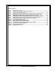
Table of Contents FCC Statement ..................................................................................................... 3 Introduction ......................................................................................................... 5 What’s New with the US2002 ............................................................................. 5 Description ........................................................................................................... 6 Features .................
Index of Figures Figure 1. Figure 2. Figure 3. Figure 4. Figure 5. Figure 6. Figure 7. Figure 8. Figure 9. Figure 10. Figure 11. Figure 12. Figure 13. Figure 14. Figure 15. Figure 16. US2002 Reference View ............................................................................................................. 7 Locations of Configuration Jumpers and Switches ................................................................ 9 Audiocom RMK Rack Mount Kits .................................................
Introduction Thank you for purchasing the Audiocom US2002 Intercom User Station. We hope the many design features of this product will satisfy your intercommunication requirements for many years to come. To get the most out of your new intercom station, please take a few moments to look through this booklet before using the US2002 for the first time. What’s New with the US2002 • New internal mechanical design in the panel mic to standardize and improve connectibility.
Description The US2002 Intercom User Station is designed for stationary use by personnel who may require selective access to two or more intercom channels. It can be rack mounted or used as a desktop station. For rack mounting, optional hardware is required. For desktop use, four rubber feet are supplied. The US2002 can be used as a simple, multichannel user station.
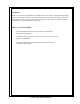
Features 1. 2. 3. 4. 5. 6. 7. 8. 9. 10. 11. 12. 13. 14. 15. 16. 17. DYNAMIC-MIC HEADSET CONNECTOR: Accepts headsets with monaural headphones and either a balanced or unbalanced dynamic microphone. PANEL MIC / ELECTRET-MIC HEADSET CONNECTOR: Accepts an electret gooseneck micro phone, such as the Telex Model MCP-90-XX. The Model MCP-90 series panel mic connector is a 1/4" stereo plug, with a threaded shaft for easy installation. VOLUME CONTROL: Adjusts headphone volume only.
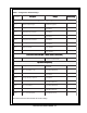
Installation Unpacking The package contains the following items. Contact the shipper or your Audiocom dealer immediately if anything is damaged or missing. Detach and fill out the registration card and return it to Telex to properly register your US2002.
Table 1.
Headset Microphone Type Selection DIP Switch SW1-1 applies only to a dynamic-mic headset connected to the dynamic-mic headset jack on the front panel. If the headset specifications indicate the microphone type is balanced, or if you are unsure, leave this switch in the off (default) position. If the specifications indicate an unbalanced microphone set SW1-1 to on. ☞ For best results in noisy environments, a noise canceling (directional or cardioid) microphone is highly recommended.
Monaural or Binaural Operation DIP Switches The US2002 can be used with a single speaker or monaural headphones (single- or double-sided) for monaural operation. In this case, all audio signals are combined and sent to the headphones and the Speaker 1 jack on the back panel. The US2002 can also be used with two speakers for binaural operation. In this case, channel 1 is sent to the Speaker 1 jack and channel 2 is sent to the Speaker 2 jack. Binaural headphone operation is not supported.
Mounting Configurations The US2002 can be used on a desktop, or it can be rack mounted. For desktop use, install the 4 rubber feet supplied with the US2002. For rack mounting, use optional Audiocom RMK Rack Mount Kits (Figure 3). ☞ You will have to perform the sidetone adjustment (page 28) after all components are connected. However, when the US2002 is rack mounted, you may not be able to access the sidetone trimmers. In this case, you can position the US2002 in the rack and make all required connections.
All Locally Powered Stations Any US2002 can be locally powered by connecting a PA-KP Local Power Supply. This is shown as an option in Figures 4 through 12. A special case is an intercom system where all stations are powered from local power supplies, with no central power supply. This is illustrated in Figure 13, page 25. External Program Input and PA Output Connections for external program input and PA output are shown in Figure 14, page 26.
7. Shielded patch cable, 9-pin Male Dsub to 9-pin Female Dsub. Customer local pur chase: available at Radio Shack, etc. Note: All pins must be connected straight through: do not use an RS232 computer cable! 8. Shielded patch cable, stereo miniplug to stereo miniplug. Customer local purchase. Available at Radio Shack, etc. 9. Shielded audio cable. Must have male 3-pin XLR connector at one end for connect ion to the XP-USPG or XP-4PGM program inputs.
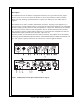
Note: For further information about the cable numbers, see page 14. Note: A BOP-1000 may be used to rack mount 2 TW-7W splitters. Figure 4. US2002 Monaural Master Speaker Station Configuration with 1 Power Supply. This is a good configuration for smaller intercom systems when you want to operate the US2002 as a master speaker station, with one speaker to monitor both intercom channels. In this configuration, the SPS2001 Combine/Isolate switch is set to the isolate position.
Note: For further information about the cable numbers, see page 14. Note: A BOP-1000 may be used to rack mount 2 TW-7W splitters. Figure 5. US2002 Binaural Master Speaker Station Configuration with 1 Power Supply. This is a good configuration for smaller intercom systems when you want to operate the US2002 as a master speaker station, with a separate speaker for each intercom channel. Make sure the US2002 internal DIP switches are set for binaural speaker operation as described on page 10.
Note: For further information about the cable numbers, see page 14. Note: A BOP-1000 may be used to rack mount 2 TW-7W splitters. Figure 6. US2002 Master Headset Station Configuration with 1 Power Supply. This is a good configuration for smaller intercom systems when you want to operate the US2002 as a master headset station. In this configuration, the PS2001L Combine/Isolate switch is set to the Isolate position. With this setting the 2 intercom channels are completely separated.
Note: For further information about the cable numbers, see page 14. Note: A BOP-1000 may be used to rack mount 2 TW-7W splitters. Figure 7. US2002 Monaural Master Speaker Station Configuration with 2 Power Supplies. This is a good configuration for large intercom systems when you want to operate the US2002 as a master speaker station, with one speaker to monitor both intercom channels. In this configuration, the SPS2001 and PS2001L Combine/Isolate switches are set to the Combine position.
Note: For further information about the cable numbers, see page 14. Note: A BOP-1000 may be used to rack mount 2 TW-7W splitters. Figure 8. US2002 Binaural Speaker Station Configuration with 2 Power Supplies. This is a good configuration for large intercom systems when you want to operate the US2002 as a master speaker station, with a separate speaker for each intercom channel. In this configuration, the SPS2001 Combine/Isolate switches are set to the Combine position.
Note: For further information about the cable numbers, see page 14. Note: A BOP-1000 may be used to rack mount 2 TW-7W splitters. Figure 9. US2002 Headset Station Configuration with 2 Power Supplies. In this configuration, the PS2001L Combine/Isolate switches are set to the Combine position. With this setting all intercom stations connected to the one PS2001L are combined on intercom channel 1 and all intercom stations connected to the other PS2001L are combined on channel 2.
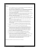
Note: For further information about the cable numbers, see page 14. Figure 10. Typical Remote Headset Station. In this example, the US2002 is not located near the system power supplies (SPS-2001, PS-2001L, etc.). The PA-KP local power supply is optional and can be used to power a single intercom station. When a PA-KP is connected to the US2002, the US2002 automatically disconnects from system power. This makes more system power available for belt packs and other intercom stations.
Note: For further information about the cable numbers, see page 14. Figure 11. Typical Remote Monaural Speaker Station. This example is similar to the one on the previous page, except a Telex MCP-90-XX microphone and a SPK-2000 speaker are used instead of a headset. Make sure the internal DIP switches are set for monaural speaker operation (default setting) as described on page 10. A PA-KP local power supply is required for the SPK-2000, but is optional for the US2002.
Note: For further information about the cable numbers, see page 14. Figure 12. Typical Remote Binaural Speaker Station. This example is similar to the one on the previous page, except that each channel is heard in a separate speaker. Make sure the internal DIP switches are set for binaural speaker operation as described on page 10. As in the previous example, a PA-KP local power supply is required for each SPK-2000 speaker, but is optional for the US2002.
Note: For further information about the cable numbers, see page 14. Figure 13. An example of all locally powered US2002 intercom stations. In this example, all components are locally powered using PA-KP local power supplies. Note the use of one termination plug in each intercom channel. (One termination plug is supplied with each US2002.) Only one termination plug should be installed per channel. Typically, they are installed at the first intercom station in the chain.
Note: For further information about the cable numbers, see page 14. Figure 14. External Audio Input and PA Output. You can connect two audio sources to the Program Inputs connector: one for each channel. Audio sources can be directly connected with a user-supplied DB9M connector. (Refer to the program input connector specifications, located on page 34, for connector pin-out.) However, a more convenient method is to use an XP-USPG Breakout Panel as shown.
Figure 15.
Power-Up Check Plug in any PA-KP local power supplies that are being used, and also turn on any system power supplies that are being used. When power is first applied to the US2002, it will perform a power-up reset, in which the front panel indicators will cycle through all of their possible colors and then turn off. This verifies the general operation of the intercom station and indicators. The US2002 also reads the settings of all DIP switches at this time and configures itself accordingly.
If you are using headphones that completely enclose the ears, adjust sidetone as follows: 1. Tap the Headset key to turn the headset microphone on. 2. Tap the channel 1 Talk key to turn it on. 3. While speaking into the microphone, use a small flat-bladed screwdriver to adjust the channel 1 sidetone so that you hear your voice at an acceptable level in the head phones. Tap the channel 1 Talk key to turn it off when finished. 4.
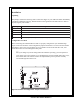
Figure 16. US2002 Bottom View Voice-Activated Microphone (Vox) Setup If you are going to use vox, you must adjust the vox level for proper operation. If the vox level is too low, room noise will activate the microphone. If the vox level is too high, the microphone will not activate when you begin talking. Check and set the level as follows: 1. If you are using a headset, tap the Headset key twice to turn on headset vox.
Operation ☞ A quick-reference to the following operating features can be found on the inside of the back cover. Normal vs Programming Mode The US2002 has two operating modes: normal operating mode and programming mode. In normal operating mode, the Mic Kill key will be unlit, and in programming mode it will be lit continuously. To return the US2002 to normal operation if it has been left in programming mode, tap the Mic Kill key.
Microphone Mute During Talk You can mute the microphone while talking. Simply tap either the Headset key or the Panel Mic key, whichever is currently being used. Tap the key again to turn the microphone back on. (If you are using Vox, tap the key twice to reactivate vox.) All Talk You can talk to all intercom stations that currently have their listens activated. This applies to both channels of the US2002 as well as all talk channels of any connected ES4000A Expansion Stations. Use All Talk as follows: 1.
Using Mic Kill If the Mic Kill feature has been enabled (page 10) you can use it to deactivate all talk keys on a single channel or on all channels. This feature is useful when a remote talk key has been left on and is causing unwanted noise on a channel. Use Mic Kill as follows: 1. Tap the Mic Kill key. It will blink green. 2. Tap the Talk or Listen key for a channel to turn off all talk keys on that channel. Or, tap the All Talk key to turn off all talk keys.
Specifications General Power Requirements: Phantom Power: 24 VDC nominal (12 to 30 VDC), 65 to 150 mA Local Power: 12 to 15 VDC, 65 to 150 mA Dimensions: 1.75" (44.5 mm) high x 8.25" (209.5 mm) wide x 10.31" (261.9 mm) deep Weight: approximately 2lb (0.
Intercom Channels, Balanced Mode (SW2 set to BAL position) Output Level: 1 Vrms nominal Input Impedance: 300 ohms Bridging Impedance: greater than 10,000 ohms Sidetone: -40 dB, 35 dB adjustable range Call Signaling: Send: 20 kHz ±100 Hz, 0.5 Vrms ±10% Receive: 20 kHz ±800 Hz, 100 mVrms Mic-Kill Frequency: Send: 24 kHz ±300 Hz, 0.
External Power Type: 2.0 mm power jack Internal pin: positive (+) External shell: negative (-) Headphone Amplifier Voltage Gain: 30 ±3 dB Maximum Output: 250 mW ±10% into 150 ohms, 65 mW±10% into 600 ohms Frequency Response: 200 Hz to 8 kHz +1/-3db Incoming Call Beep Tone: 2 kHz, at the headphones Total Harmonic Distortion: Less than 0.
Factory Service and Parts Information When returning equipment for repair include your return address, telephone number and proof of date of purchase, along with a description of the problem.* The address for Audiocom equipment returns and parts information is: Service Department Telex Communications, Inc. West 1st Street Blue Earth, Minnesota 56013 U.S.A. Telephone: (507) 526-3205 (Collect calls not accepted) Warranty Repairs - If in warranty, no charge will be made for the repairs.
This page intentionally left blank Intercom User Station US2002 - 38
Table 3. Quick Reference Reset US2002 Press All Talk and Listen 1. Reset ES4000A Press All Talk 4 and Listen 5. Test signal on Press All Talk and PA, then tap Call. Test signal off Tap Call, then tap any other key. Mic latched on Tap Headset or Panel Mic (key is green). Mic latched off Tap Headset or Panel Mic. Mic momentary on Hold Headset or Panel Mic. Mic momentary off Release Headset or Panel Mic. VOX mode on Tap twice: Headset or Panel Mic (key is orange).
9350-7748-000 Rev.