Telex® User Instructions 0A 00 S2 SP 1 2 e um l Vo R Model SPS2000A Power Supply Audiocom ® Intercom Systems ® T SE RE
FCC Statement This equipment uses, and can radiate radio frequency energy that may cause interference to radio communications if not installed in accordance with this manual. The equipment has been tested and found to comply with the limits of a Class A computing device pursuant to Subpart J, Part 15 of FCC Rules which are designed to provide reasonable protection against such interference when operated in a commercial environment.
Table of Contents Description . . . . . . . . . . . . . 4 Installation . . . . . . . . . . . . . 6 Unpacking . . . . . . . . . . . . 6 Configuration Switches . . . . . . . . . . 6 . . . . . 6 Intercom Channel and Program Connections Power-Up Check . Specifications . . . . . . . . . . . . 11 . . . . . . . . . . 13 . . . . . . .
Audiocom® Description The SPS2000A is a versatile power supply that can be used in a variety of Audiocom® intercom system applications. It is ideal for applications where it is desirable to use a master station with a panel mic / speaker combination. The SPS2000A directly accepts any AC input power from 100 to 240 VAC, 50/60 Hz, and it can be configured to power two separate intercom channels or one large intercom channel with twice the intercom station capacity.
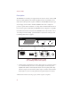
2. Combine / Isolate Switch: This recessed, pushbutton switch lets you combine the audio signals of the two channels to create a single audio channel where all users can intercommunicate. Or, you can isolate each channel to create two groups of completely independent users. 3. Channel Status Indicators and Reset Pushbutton: The indicators are green for normal operation and red when there is an overload or short circuit.
Audiocom® Installation Unpacking The package contains the following items. Contact the shipper or your Audiocom dealer immediately if anything is damaged or missing. Detach and fill out the registration card and return it to Telex to properly register your SPS2000A.
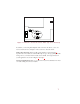
Figure 2. Audiocom / Clear-Com Selector Switch (Top Cover Removed) Note that if you are using DC wallpacks with some intercom stations, you do not need to add the current consumption of those stations to the total current. Audiocom Connections: Intercom cable wiring details are shown in Figure 3. Speaker interconnect cables are standard RCA phono types. For program input cable wiring, refer to your master intercom station user manual.
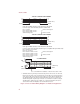
Audiocom® TYPICAL 1-CHANNEL CABLE WIRING 3 2 Pair 1 3 2 1 Pair 2 1 (Both wires) Shield Shield Cable Type: 22AWG Stranded, 2-Pair Twisted-wire, with Shield Connector Type: 3-Pin XLR Audio (Neutrik or Switchcraft)* Pin 1: Common Denotes twisted pair. Pin 2: Channel Audio / Power Pin 3: Channel Audio / Power Denotes shield.
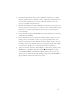
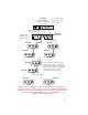
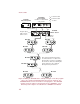
SPS2000A Power Supply Combine / Isolate Switch set to Isolate 1 1-channel cable 2 2-channel cable Y “Y” cable SPEAKER INPUT 1 ® INPUT 2 100-240 VAC 60/50 HZ CHN 1 LINE LEVEL 1 VRMS Speaker Interconnect cable. Program Input cable. From 2 audio sources MADE IN USA 1 1 PUSH US2000A Master Station PUSH PROGRAM INPUTS + SPEAKERS LINE LEVEL 1 VRMS - 1 VOL PGM 1 VOL PGM 2 2 P.A.
Audiocom® SPS2000A Power Supply Combine / Isolate Switch set to Isolate SPK1000 Powered Speaker TELEX COMMUNICATIONS, INC. MADE IN USA 1 1-channel cable 2 2-channel cable Y “Y” cable SPEAKER INPUT 1 INPUT 1 + - ® INPUT 2 INPUT 2 100-240 VAC 60/50 HZ BAL CHN 1 LINE LEVEL 1 VRMS 12-15 VDC LINE LEVEL 1 VRMS Speaker interconnect cables. Program input cable.
SPS2000A Channel 2 Power Combine / Isolate Switch set to Combine SPS2000A Channel 1 Power Combine / Isolate Switch set to Combine SPEAKER SPEAKER INPUT 1 INPUT 1 ® ® INPUT 2 100-240 VAC 60/50 HZ INPUT 2 100-240 VAC 60/50 HZ CHN 1 LINE LEVEL 1 VRMS CHN 2 CHN 1 MADE IN USA LINE LEVEL 1 VRMS CLASS 2 WIRING 1.5A 24VDC CHN 2 MADE IN USA CLASS 2 WIRING 1.5A 24VDC 1 1 Speaker interconnect cables. PUSH PUSH PROGRAM INPUTS + SPEAKERS LINE LEVEL 1 VRMS - 1 VOL PGM 1 VOL PGM 2 2 P.A.
Audiocom® 2. Plug in the AC power cords for any connected SPS2000A Power Supplies. The channel status indicators should be green. 3. If a channel status indicator turns red during operation, try correcting the problem by pressing the reset button on the front of the SPS2000A. If the problem persists, unplug the SPS2000A and locate the short or overload that is causing the problem.
Specifications General Input Power Requirements: 100 to 240 VAC, 50 / 60 Hz Output Power (each channel) 21 ± 1 VDC, 2A Dimensions: 1.75" (44.5 mm) high x 8.25" (209.5 mm) wide x 10.31" (261.9 mm) deep Weight: approximately 2.5 lb (1.13 kg) Environmental Requirements: Storage: -20°C to 80°C; 0% to 95% humidity, non-condensing Operating: 0°C to 50°C; 0% to 95% humidity, non-condensing Intercom Channels General Connector Type: One XLR-3M audio connector for each channel.
Audiocom® Factory Service and Parts Information When returning equipment for repair include your return address, telephone number and proof of date of purchase, along with a description of the problem.* The address for Audiocom equipment returns and parts information is: Service Department Telex Communications, Inc. West 1st Street Blue Earth, Minnesota 56013 U.S.A. Telephone: (507) 526-3205 (Collect calls not accepted) Warranty Repairs - If in warranty, no charge will be made for the repairs.
Notes 15
® TELEX COMMUNICATIONS, INC. 9350-7333-010 Rev. A 2 , 8/97 9600 Aldrich Ave. So., Minneapolis, MN 55420 U.S.A.