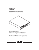
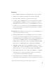
Telex® User Instructions 000A ES4 n Liste Call isten L n Liste Talk Call Talk Talk Talk 5 Call n Liste ® Call 4 3 Model ES4000A Intercom Expansion Station Audiocom ® Intercom Systems ® 6
FCC Statement This equipment uses and can radiate radio frequency energy that may cause interference to radio communications if not installed in accordance with this manual. The equipment has been tested and found to comply with the limits of a Class A computing device pursuant to Subpart J, Part 15 of FCC Rules which are designed to provide reasonable protection against such interference when operated in a commercial environment.
Table of Contents Description . . . . . . . . . . . . . 4 Features . . . . . . . . . . . . . . 5 Installation . . . . . . . . . . . . . 7 Unpacking . . . . . . . . . . . . 7 Configuration Pre-check . . . . . . . . . . 7 Mounting Configurations . . . . . . . . . 10 Connection Notes . . . . . . . . . . . 13 Cables . . . . . . . . . . . . . 22 Power-Up . . . . . . . . . . . .
Audiocom® Description The ES4000A is an Expansion Station for the US2000A User Station. It interfaces 4 additional intercom channels to the US2000A, and it provides talk, listen and call buttons for the 4 additional channels. There are also 4 additional program inputs on the back of the ES4000A, 1 for each added channel. Up to 4 ES4000A Expansion Stations may be connected to the US2000A to add up to 16 channels (18 channels total).
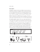
Features 1. Intercom Talk Keys: Momentary or latching (hands-free) operation possible. 2. Call Keys: Used to call intercom channels and to indicate incoming calls. 3. Intercom Listen Keys: Momentary or latching operation possible. 4. Local Power Jack: The ES4000A can be powered from the intercom channels via the CHANNEL 3-6 OUTPUTS connector (9). Alternatively, an optional PS-L wall-pack accessory may be used to power the ES4000A from an AC outlet.
Audiocom® nal jumper which routes the program either to the intercom channel only, or to both the intercom channel and the US2000A headset or speaker (default setting). Additionally, the program signal to the intercom channel may be turned on or off via the US2000A front panel programming. There is also an internal program interrupt DIP switch which selects either automatic program interrupt when the station operator activates a channel's talk key, or no program interrupt during talk.
Installation Unpacking The ES4000A is supplied with the following items. Contact the shipper or your Audiocom dealer immediately if anything is damaged or missing. Detach and fill out the registration card and return it to Telex to properly register your intercom station. Quantity 1 1 1 2 1 1 4 Description ES4000A Expansion Station Warranty and registration card User Instructions Termination Plug EXP IN/OUT Cable, with 1/8-inch (3.
Audiocom® Table 1.
Audiocom Call Send and Receive DIP Switches By default, all channels of the ES4000A can send and receive Audiocom call signals. You can disable call send or call receive capability for selected channels if desired. ☞ When the BAL / UNBAL switch on the back panel is set to the UNBAL position (for use with a Clear-Com Intercom System) the call send and call receive DIP switches have no effect. Call send and call receive are always on for Clear-Com usage.
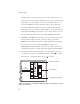
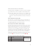
Audiocom® Sidetone Trimmers These trimmers are normally adjusted after all components are connected, and they can be accessed through the bottom cover (Figure 15). Refer to the US2000A User Manual for the sidetone adjustment procedure. Mounting Configurations The ES4000A can be used on a desktop, or it can be rack mounted. For desktop use, install the 4 rubber feet supplied with the ES4000A. For rack mounting, use optional Audiocom RMK Rack Mount Kits (Figure 3).
FRONT OF RACK BACK OF RACK PS4000 (CH7 -10POWER) PS-4000 ® 1 2 SPS2000A (CH1/2 POWER) PS-4000 Combine Isolate 1 2 2 Reset US2000A ® Headset Listen Mic Kill Reset ® 1 Volume 4 PS4000 (CH3 -6POWER) SPS2000A ® 3 3 4 Reset ES4000A ® Listen Listen Listen Listen Listen Vox All Talk Volume Call PA Panel Mic XP-USPG XP-4PGM XP-4PGM SPARE BOP-1000 WITH 1 XP-USPG AND 1 XP-4PGM Call Talk Call Talk 1 Call Talk Call Talk 2 Call Talk 3 Talk 4 5 6 ES4000A ® US
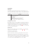
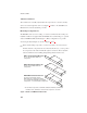
BACK OF RACK FRONT OF RACK PS2000L (CH6 POWER) PS2000L ® PS2000L ® 1 Combine Isolate 1 2 Combine Isolate Reset PS2000L (CH3 POWER) PS2000L ® 1 Combine Isolate BOP-1000 WITH 1 XP-USPG, 1 XP-4PGM, AND 1 XP-ES4000 1 2 Combine Isolate Reset SPS2000A (CH1 POWER) 2 PS2000L ® 1 1 Combine Isolate 2 Combine Isolate Reset US2000A ® Headset Listen Mic Kill Reset PS2000L (CH2 POWER) SPS2000A ® Volume Reset PS2000L (CH4 POWER) PS2000L ® 2 Listen 2 Reset ES4000A ® Listen
Connection Notes • Typical connections for the US2000A, ES4000A and various power supplies are shown starting with Figure 6, page 14. Select the configuration which most closely matches your intended usage. • The US2000A and ES4000A normally draw operating power from the intercom channel power supplies (SPS2000A, PS2000L, etc.). Alternatively, you can use optional PS-L Wall-pack Power Supplies.
Audiocom® PGM PGM 2 IN 1 IN 9 PA OUT 9 CH 1-2 SPS2000A 10 SPEAKER INPUT 1 ® 100-240 VAC 60/50 HZ INPUT 2 CHN 1 CHN 2 MADE IN USA LINE LEVEL 1 VRMS 4 FRONT CH 1-2 XP-USPG 1 1 US2000A PUSH PUSH PROGRAM INPUTS + 1 SPEAKERS LINE LEVEL 1 VRMS - VOL PGM 1 VOL PGM 2 2 P.A.
SPS2000A Channel 1 Power and All-Channel Speaker Combine / Isolate Switch set to Combine PS2000L Channel 2 Power Combine / Isolate Switch set to Combine SPEAKER INPUT 1 ® ® INPUT 2 100-240 VAC 60/50 HZ 100-249 VAC 60/50 HZ CHN 1 CHN 2 CHN 1 MADE IN USA LINE LEVEL 1 VRMS CHN 2 MADE IN USA 1 4 1 PUSH PUSH PROGRAM INPUTS + SPEAKERS LINE LEVEL 1 VRMS - 1 VOL PGM 1 VOL PGM 2 2 P.A.
Audiocom® TO US2000A EXP IN CONNECTOR Note: For further information about the cable numbers, see page 22.
TO US2000A EXP IN CONNECTOR Note: For further information about the cable numbers, see page 22.
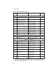
Audiocom® TO US2000A EXP IN CONNECTOR Note: For further information about the cable numbers, see page 22. 5 CH 3-6 ES4000A Telex SPEAKERS + - EXP IN EXP OUT 5 4 6 LINE LEVEL 1 VRMS 12-15 VDC XP-ES4000 ® 3 PROGRAM INPUTS PGM VOLUME 3 BAL-OUT UNBAL-IN 4 5 CAN 3-6 OUTPUTS 6 5 BACK TO THE EXP IN CONNECTOR OF ANOTHER ES4000A 6 1 CH 6 1 CH 5 1 FRONT PUSH CH 4 1 PUSH CH 3 PUSH PUSH TO 1/2 OF REMOTE MASTER STATIONS AND BELT PACKS ON CH 3 AND CH 4.
PS-L SPK2000 CH 1-2 US2000A 4 1 - + SPEAKERS LINE LEVEL 1 VRMS - INPUT2 P.A.
Audiocom® TO US2000A EXP IN CONNECTOR 5 Note: For further information about the cable numbers, see page 22.
SPK2000 SPK2000 CH 1-2 US2000A 4 + PUSH PROGRAM INPUTS INPUT1 - + PUSH P.A. 12-15 VDC ® 1 SPEAKERS LINE LEVEL 1 VRMS - VOL PGM 1 INPUT2 BAL + VOL PGM 2 - + BAL - OUT UNBAL - IN BAL CHN 2 CHN 1 5 P.A.
Audiocom® Cables The numbers below correspond to the cable numbers in the connection drawings on the previous pages. 1. 1-channel intercom cable. Sold separately. Use Telex "ME" cables, below. Or, build per Figure 14. ME-25: 25' (7.6 m) cable with Male and Female 3-pin XLR connectors. ME-50: 50' (15.2 m) cable with Male and Female 3-pin XLR connectors. ME-100: 100' (30.4 m) cable with Male and Female 3-pin XLR connectors. 2. 2-channel intercom cable. Sold separately. Use Telex "ME /2" cables, below.
9. Shielded audio cable. Must have male 3-pin XLR connector at one end for connection to the XP-USPG or XP-4PGM program inputs. Pin-out for program inputs is as follows: Pin 1: common Pin 2: + program input Pin 3: - program input 10. Shielded audio cable. Must have male 3-pin XLR connector at one end for connection to the XP-USPG PA output.
Audiocom® TYPICAL 1-CHANNEL CABLE WIRING 3 2 Pair 1 3 2 1 Pair 2 1 (Both wires) Shield Shield Cable Type: 22AWG Stranded, 2-Pair Twisted-wire, with Shield Connector Type: 3-Pin XLR Audio (Neutrik or Switchcraft)* Pin 1: Common Denotes twisted pair. Pin 2: Channel Audio / Power Pin 3: Channel Audio / Power Denotes shield.
Ch 3 Sidetone Ch 4 Sidetone Ch 5 Sidetone Ch 6 Sidetone Figure 15. Sidetone Trimmer Access on Bottom of ES4000A Power-Up The ES4000A channels power-up identically to channels 1 and 2 of the US2000A. Refer to the US2000A User Instructions for all power-up information. Sidetone Adjustments Use the sidetone adjustment procedure as described in the US2000A User Instructions, except substitute channel 3, channel 4, etc. The locations of the ES4000A sidetone trimmers are shown in Figure 15.
Audiocom® Specifications General Power Requirements: Voltage: Phantom Power: 24 VDC nominal (12 to 30 VDC) Local Power (with PS-L Wall-pack Power Supply or equivalent): 14 to 15 VDC Current: 65 mA, quiescent; 150 mA maximum Dimensions: 1.75" (44.5 mm) high, 8.25" (209.6 mm) wide, 10.
Frequency Response EXP IN to/from Channel, EXP IN to/from EXP OUT, Channel to Speaker: 200 Hz to 8 kHz +1/-3 dB Total Harmonic Distortion: Less than 0.5 % Connector Pin-outs 12-15 VDC Jack Connector Type: 2.0 mm DC jack Internal pin: + 12 to 15 VDC External Ring: Common EXP IN Jack Connector Type: 1/8" (2.0 m) stereo phone jack Tip: Listen input Ring: Talk output Sleeve: Common EXP OUT Jack Connector Type: 1/8" (2.
Audiocom® CHANNEL 3-6 OUTPUTS Connector Connector Type: DB15F Female, 15-pin D-subminature Pin 1: Channel 3 intercom audio input/output high Pin 2: Channel 3 intercom audio input/output low Pin 3: Common Pin 4: Channel 5 intercom audio input/output high Pin 5: Channel 5 intercom audio input/output low Pin 6: Common Pin 7: Common Pin 8: Common Pin 9: Common Pin 10: Channel 4 intercom audio input/output high Pin 11: Channel 4 intercom audio input/output low Pin 12: Common Pin 13: Channel 6 intercom audio inpu
Factory Service and Parts Information When returning equipment for repair include your return address, telephone number and proof of date of purchase, along with a description of the problem.* The address for Audiocom equipment returns and parts information is: Service Department Telex Communications, Inc. West 1st Street Blue Earth, Minnesota 56013 U.S.A. Telephone: (507) 526-3205 (Collect calls not accepted) Warranty Repairs - If in warranty, no charge will be made for the repairs.
Audiocom® Notes 30
Notes 31
Addendum Document Affected: ES4000A User Instructions, Publication Number 9350-7551-000 Rev. A Addendum Number: 1 General Instructions: Use this addendum with Revision A of the user instructions. This information will be included in Revision B. Page 6, item 6: The description should be 18" (457 mm) CHANNEL OUTPUT cable, 15-pin Male Dsub to 15-pin Male Dsub. One supplied with each ES4000A. Pages 16-21: All cables labeled with number 6 should be labeled with number 11.
® TELEX COMMUNICATIONS, INC. 9350-7551-000 Rev. B , 8/00 12000 Portland Ave. So., Burnsville, MN 55337 U.S.A.