Operating Manual BTR-24 TR-24 Wireless Intercom System Bosch Communications Systems
Table of Contents Section 1 Introduction . . . . . . . . . . . . . . . . . . . . . . . . . . . . . . . . . . . . . . . . . . . . . . . . . . . . . . . . . . . . . . . . . 1-1 General Description. . . . . . . . . . . . . . . . . . . . . . . . . . . . . . . . . . . . . . . . . . . . . . . . . . . . . . . . . . . . . . . . . . . . . 1-1 System Features. . . . . . . . . . . . . . . . . . . . . . . . . . . . . . . . . . . . . . . . . . . . . . . . . . . . . . . . . . . . . . . . . . . . . . . .
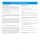
Section 1 - Introduction General Description System Features The Telex BTR-24 System is a full duplex (simultaneous talk and listen), multi-channel, wireless intercom system. The system offers a complete solution for up to 10, full duplex users per base station, many more if in push-to-transmit mode. With fast and easy set-up, durable beltpacks, 64 bit audio encryption, and professional grade headsets. • • • No FCC License required.
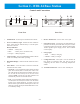
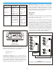
Section 2 - BTR-24 Base Station Controls and Connections 1 2 3 Telex ON 4 5 R LOW BATTERY 9 10 8 BTR-24 Telex Communications, Inc. SELECT POWER OFF 7 6 This device complies with Part 15 of the FCC Rules Operation is subject to the following two conditions (1) This device may not cause harmful interference, and (2) This device must accept any interference, received. Including interference that may cause undesired operation.
Section 3 - TR-24 Beltpack Controls and Connections 12 3 4 5 OFF 1 MIC A DJ S.T. A DJ 67 8 CHG 2 EXT Bottom View Top View 1. Volume Control and Power Switch – Turns the beltpack power on/off and controls headset volume. 2. Battery Light/Power Light – Indicates the beltpack has power, either from the internal battery or AC power connected to the unit. 6. Charge Jack – Used to charge the internal battery or power unit directly off wall outlet. Accepts a 5.5mm x 2.
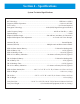
Section 4 - Specifications System Technical Specifications RF Technology............................................................................................................IEEE 802.11 (WiFi) Frequency Band of Operation ......................................................................................2.412 to 2.462 GHz FCC License ..............................................................................................................No License Required Encryption Technology................
Section 5 - Operation Multiple base stations can also be utilized in an installation. The base stations have the ability to communicate to each other via an Ethernet network connected to the RJ-45 jack on the rear panel. The connection between bases could be a direct connection via an Ethernet cable (100m, 328ft Max.) or connected via the building’s Ethernet infrastructure (See “Network Information” in the “Wired Mode” discussion for details.).
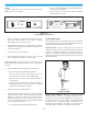
• After 20 seconds a beltpack voice prompt will announce Set-up “wireless” in the headphone. Below are instructions for the set-up and operation of a single BTR-24 with up to ten TR-24's. • Audio channel one’s light will activate indicating communication has started. Telex ON R BTR-24 Telex Communications, Inc.
Mode Push-to-Latch/ Momentary (default mode) Momentary Only (Push-to-TX) Description Activation Microphone is enabled until the button is tapped again. If held down for 1/2 second the microphone path is disabled on release. Tap button. Tap again to turn off. button enables the audio path for only as long as it is held down. The beltpack will be in this mode until reset to push-to-latch mode. Press <1> + + <2> until voice prompt indicates momentary mode (about 3 seconds).
Up to ten beltpacks, in full duplex (simultaneous talk and listen), may communicate with each other over a Ethernet network. In fact do to the flexibility of the BTR-24 system, wired beltpacks connected via a hub to a network could communicate to a BTR-24 connected to the same network. This base station could then be connected wirelessly to other TR-24s operating in wireless mode. 4. Plug headsets into the TR-24 beltpacks. 5. Power-up the TR-24 beltpacks in wired mode.
The sidetone (amount of your own voice fed back to your earphones) and microphone gain of the beltpacks may need adjusted from the factory defaults. The defaults are: Description • Microphone Level = 4 • Sidetone Level =2 Microphone Level Adjust – Press <1> + until a voice prompt indicates microphone adjust mode has been entered (about 3 seconds). Keep holding down and use the <1> button to decrease the level, <2> button to increase the level.
2. Plug the master TR-24’s external power supply into an AC outlet if desired. If external power is not desired then run off internal battery. 3. Place the TR-24’s in a location where it will have the best visibility to the other TR-24s. 4. Plug a headset into the master TR-24 beltpack. 5. Power-up the master TR-24 beltpack in master wireless mode. The master wireless mode is entered by holding the <1> button down as the unit boots.
The sidetone (amount of your own voice fed back to your earphones) and microphone gain of the beltpacks may need adjusted from the factory defaults.
Section 6 - Encryption Code and Password • Ethernet straight thru or crossover cable (Use the green Encryption Code cable supplied with the system.) The BTR/TR-24 system uses a 64 bit DES (Digital Encryption Standard) encryption algorithm to encrypt all audio in the system. The beltpacks in the system have a “key” that the algorithm uses as the basis for the encryption. The same “key” must be used in all beltpacks on the system for communication to occur.
10. Plug the other end of the Ethernet cable into the beltpack. 3. Enter new encryption key The user must change the encryption key if this option is selected. Since a base station acts only as a relay for the audio packets it is not necessary to change its encryption key. 11. Type, telnet 192.168.1.X at the computer’s command prompt, then press . Fill in for X the last digit of the IP address that is on the back label on the TR-24. 1.
Section 7 - Battery Care/Long Term Storage Battery Care Li-Ion Batteries To ensure the long life and safe handling of the Li-Ion battery within the BTR-24 and TR-24 please following the following precautions: The Li-Ion batteries used in the TR-24 and BTR-24 are excellent batteries for portable, indoor/outdoor applications.
Section 8 Please reread the operation and encryption/password section of this manual to make sure you have completed system set-up properly. The following contains troubleshooting tips that may be helpful in solving the problem. Problems RF range of all the beltpacks is less than normal and/or beltpacks are experiencing “break-up” of audio in an area where they have worked well in the past.
Section 8 - Troubleshooting continued Problem Possible Cause When the BTR-24 power switch was turned on nothing happens. The power light does not light. • Internal battery exhausted When the BTR-24 power switch was turned on, the unit's power light came on but the system never booted-up after 25 seconds. • Solution • Plug the AC power plug into the BTR-24. Allow the unit at least 5 minutes for the internal battery to receive an initial charge. Then turn the unit on and run it off AC power.
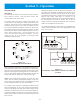
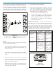
Section 9 - RF Channels 802.11 RF Channels The BTR-24 system has the ability to operate on any one of eleven RF channels. Although there are several different frequency channel settings, there is overlap between the channels. There are three non-overlapping channels available in the FCC regulatory domain. When choosing frequency channels for systems in the vicinity of each other, you should choose frequency channels that do not overlap (e.g. Channels 1, 6, and 11).
Section 10 - Regulatory Information Regulatory Information The TR-24 and BTR-24 comply with Part 15 of FCC rules and Canada RSS-210. Operation is subject to the following conditions: 1. This device may not cause harmful interference. 2. This device must accept any interference received, including interference that may cause undesired operation. 3. Use only the manufacturer or dealer supplied antenna(s), beltclips and/or accessories for this device. 4.
Section 11 - Accessories and Replacement Items Model Number Part Number Description TR-24 PRD000065000 TR-24 Beltpack and US Power Supply. NOTE: User must provide the IP address of all TR-24/BTR-24s in system with order. RPT-3 302054007 3 ft. coax with TNC reverse polarity plug connector. RPT-10 302054008 10 ft. coax with TNC reverse polarity plug connector. TNC-RP 302054009 TNC reverse polarity coupler. Coupler is a reverse polarity jack to jack.
Section 10 - Accessories and Replacement Items Continued Model Number Part Number Description BTR-24 PRD000066000 BTR-24 Base Station and US power supply. NOTE: User must provide IP address of all TR-24/BTR-24's in system with order. SYS-243 SYS000007000 System includes Carry Case, 3 TR-24 Beltpacks, 1 BTR-24 Base Station, Omni antennas, rack mounts, 3' Ethernet cable, and US power supplies.
Bosch Communications Systems 8601 East Cornhusker Highway, Lincoln, NE 68507 Made in U.S.A. PN LIT000078TX Rev.