Part No. TEL–09949, Rev A June 2001 Page 1 of 34 326X SERIES MODEM Modem Cards, Backplanes, and Modular Nest 9 and 21 Enclosures In This Notice Topic See Page Introduction ............................................................................................... About the 326X Series Modem Documentation Set............................. For More Details on the 326X Modem’s... ........................................... Safety Information..............................................................
Part No. TEL–09949, Rev A June 2001 Page 2 of 34 Overview This document covers: • Information you need and activities you must complete before installing and operating 326X Series Modem card(s) in the Modular Nest 9 and 21 Enclosure • Procedures for removing and replacing a backplane installed in a Modular Nest 9 or 21 enclosure • A procedure for testing a backplane for proper installation and connection Use this information with the Modular Nest 9 and 21 Operations and Installation Guide (Part No.
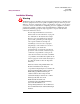
Part No. TEL–09949, Rev A June 2001 Page 3 of 34 Safety Information Safety Information This section explains how Warning Notices are used in Telenetics’ documentation, and it provides such notices for users of the 326X Series Modem. Warning Description The following notice emphasizes certain information. In documentation, it is displayed in the format shown: Warning Warning is the most serious notice, indicating that you can be physically hurt.
Part No. TEL–09949, Rev A June 2001 Page 4 of 34 Safety Information Installation Warning Warning All Telenetics devices should be used in environments designed for computers and electronic equipment. In areas susceptible to lightning, take precautions to prevent damage to electronic equipment. Contact your telephone company, or an electronic accessories vendor, for information on lightning protection equipment.
Pre-Installation Information and Activities Part No. TEL–09949, Rev A June 2001 Page 5 of 34 Pre-Installation Information and Activities This section provides information about 326X Series Modem card models 3262, 3263, 3267 and 3268. It describes activities you must complete before installing and operating 326X Series Modem card(s) in a Modular Nest enclosure. 326X Series Modem Cards and Backplanes This section describes 326X Series Modem cards and backplanes, and items shipped with them.
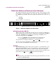
Part No. TEL–09949, Rev A June 2001 Page 6 of 34 Pre-Installation Information and Activities Stand-alone Modems and Enclosure Cards: Differences The 326X Series Modem card front panel differs from that of the stand-alone 326X Series Modem. As shown in Figure 1, the 3262, 3263, 3267, and 3268 Modem cards have eight front-panel LEDs. Stand-alone 326X Series Modems do not have two of these: 125 A/B ALM 109 108 RC/NC RI/OH 104 103 CD TR RD TD • A/B LED • ALM LED These two LEDs are described here.
Pre-Installation Information and Activities Part No. TEL–09949, Rev A June 2001 Page 7 of 34 Telephone Company Compliance—U.S.A. Models The Telenetics 326X Series Modem complies with Part 68 of the FCC rules. The modem card includes a label with the FCC registration number for this equipment. If requested by the telephone company, you must provide this information. Generally, the ringer equivalence number (REN) is also requested for telephone equipment. The REN is listed on the FCC registration label.
Part No. TEL–09949, Rev A June 2001 Page 8 of 34 Pre-Installation Information and Activities Countries That Support Busy Out Some backplanes have a Busy Out feature and are intended for use with dial modems (models 3262 and 3267). In some countries, leased modems (models 3263 and 3268) use Busy Out for dial restoral. The following table shows which countries use the Busy Out feature.
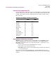
Pre-Installation Information and Activities Part No. TEL–09949, Rev A June 2001 Page 9 of 34 Make Busy backplanes are factory configured for Busy Out operation in their destination country, as indicated in Table 1 or Table 2. Table 1. Backplane Pin Settings for Busy Out, Modular Nest 9 Pin Pair Function 1 Left TIP and RING 1 Right Make Busy and Make Busy 1 1Inner U. S. A.
Pre-Installation Information and Activities Part No. TEL–09949, Rev A June 2001 Page 10 of 34 Kontaktstiftüberbrückungen sollten nur von qualifiziertem Kundendienstpersonal entfernt werden. Ein qualifizerter Kundendiensttechniker ist vertraut mit dem Betrieb des Produkts, ausgebildet für die Technologie der mit Strom versorgten Datenverarbeitung und Unternehmensgeräten sowie informiert über die Gefahren, die von diesen Geräten ausgehen können.
Part No. TEL–09949, Rev A June 2001 Page 11 of 34 Pre-Installation Information and Activities Refer to Figure 2, which shows pin locations on Modular Nest 21 backplanes. Modular Nest 9s have a similar layout. Modem A Modem B Pins Jumpers on Left Pin Pairs Pins Modular Nest 21 Enclosure, Rear View Figure 2.
Part No. TEL–09949, Rev A June 2001 Page 12 of 34 Pre-Installation Information and Activities Setting the Modem Card DIP Switch An 8-position DIP (Dual Inline Package) switch on the modem card functions the same as the rear panel DIP switch on stand-alone modems. The switches are numbered from left to right on the card (Figure 3). You must set the DIP switch before installing the card. Table 3 lists the switches and explains their use. Open (Off) is the factory default for the switches.
Pre-Installation Information and Activities Part No. TEL–09949, Rev A June 2001 Page 13 of 34 Table 3. Modem Rear Panel DIP Switch Functions Switch Number 1 (Modem A only) 7 (Modem B only) 2 (Modem A only) 8 (Modem B only) 3 (Modems A and B) 4 (Modems A and B) 5 (Modems A and B) 6 (Modems A and B) Setting Function Off EIA/TIA 232-D pin 23 is set for data rate input. Setting Switch 1 or 7 to this position has no effect on modem operation. On EIA/TIA 232-D pin 23 is set as a data indicator.
Part No. TEL–09949, Rev A June 2001 Page 14 of 34 Pre-Installation Information and Activities Cabling the 3262 and the 3267 (Dual Dial) Modem Cards Refer to Figure 4 for cabling of 3262 and 3267 (dual dial) Modem cards. Interface and cabling pin-outs vary by country. Refer to the 326X Series Modem User’s Guide, Appendix C, Country-Specific Information, for interface and cable pin-outs. For DTE and Network Control Port interface pin-outs, refer to Appendix B, Interface Pin-outs, of that guide.
Part No. TEL–09949, Rev A June 2001 Page 15 of 34 Pre-Installation Information and Activities Cabling the 3263 and the 3268 (Leased Line, Dial Restoral) Modem Cards Refer to Figure 5 for cabling of 3263 and 3268 (leased line with dial restoral) Modem cards. Interface and cabling pin-outs vary by country. Refer to the 326X Series Modem User’s Guide, Appendix C, Country-Specific Information, for interface and cable pin-outs.
Part No. TEL–09949, Rev A June 2001 Page 16 of 34 Pre-Installation Information and Activities Attaching Ferrite Beads (U.S.A., Canada, and Japan Only) A cable with an attached ferrite is included in the accessory kit for U.S.A., Canada, and Japan 326X Series Modem cards. In order to meet FCC Class A and CISPR requirements, the ferrite side of the dial and leased line cables must be attached as close to the backplane as possible (Figure 6). .
Pre-Installation Information and Activities Part No. TEL–09949, Rev A June 2001 Page 17 of 34 To release the connector: 1) Insert a small screwdriver beneath the clip on the bottom of the connector (Figure 7). 2) Press down on the screwdriver to release the clip and gently pull to remove the connector from its receptacle on the backplane.
Pre-Installation Information and Activities Part No. TEL–09949, Rev A June 2001 Page 18 of 34 326X Series Modem—Cabling to a Network Manager This section describes how to set the 326X Series Modem backplane NMS Bus DIP switches for network management. It also describes the proper sequence for connecting to a Network Management System (NMS).
Part No. TEL–09949, Rev A June 2001 Page 19 of 34 Pre-Installation Information and Activities Figure 8 shows a single NC command flow path. In the figure, the local masters receive network control from a single network manager source. Network Manager Modular Nest 9 or 21 Enclosure Backplane Modular Nest 9 or 21 Enclosure Backplane Local Master In-Connector from Backplane. In-Connector from Backplane: Not Used. Remote Master For Any Daisy-Chained Device. Local Slave For Any Daisy-Chained Device.
Part No. TEL–09949, Rev A June 2001 Page 20 of 34 Pre-Installation Information and Activities A group’s network management signaling is passed along a multi-drop bus in the backplane to each NC port. One slot of each group is the Bus Master slot (NC 1 for group 1, NC 2 for group 2, etc.). The group number is identified by the Bus Master slot number (e.g., Group 1 uses Bus 1 Master slot). For a group’s NC port to work, its Bus Master slot must be occupied. Figures 9 and 10 show this for each backplane.
Part No. TEL–09949, Rev A June 2001 Page 21 of 34 Pre-Installation Information and Activities NC Port and Bus Master Slots Are within Shaded Areas NC MSTR 2 NC BUS IN COMM OUT NC MSTR 2 NC BUS IN OUT +5V +12V -12V NC BUS NC MSTR 2 IN OUT OUT NC MSTR 1 AC POWER Network Control Group 4 Network Control Group 3 Network Control Group 2 Network Control Group 1 Figure 10.
Pre-Installation Information and Activities Part No. TEL–09949, Rev A June 2001 Page 22 of 34 Setting Control Across Groups You can use cables to daisy-chain NC ports on 326X Series Modem cards, as you can with stand-alone modems. With 9- and 21-card backplanes, you can also set NMS Bus DIP switches on the backplane so that all NC signaling is bussed to one NC Port.
Part No.
Part No. TEL–09949, Rev A June 2001 Page 24 of 34 Pre-Installation Information and Activities If the application requires more NC slaves than the larger backplanes have groups, connect multiple backplanes in the enclosure using the 1-card backplane. When combining backplanes in an enclosure, one modem card slot is lost for each type of backplane that is used. For example, two 9-modem card backplanes in an enclosure occupy 19 slots.
Part No. TEL–09949, Rev A June 2001 Page 25 of 34 Pre-Installation Information and Activities There are two ways to determine your modem’s software revision number. From the modem front panel: 1) Press the appropriate front panel control key (from your location in the configuration menu structure) until the following (for example) appears: Data 9600 T/D? 2) Press until the Operating Status appears (for example): DTE 19.2 RELIABL 3) Press until the following appears: Display Modem ID 4) Press .
Pre-Installation Information and Activities Part No. TEL–09949, Rev A June 2001 Page 26 of 34 Preparing the 9110 DMS for 326X Series Card Modems When managing 326X Series Modems in an enclosure using the 9110 Dial Management System (DMS), set the Use option (in the 9110 Comm Port Definition screen) to Complete. This configures the 9110 to poll all modems (see “Polling” in Chapter 1 of the 9110 DMS User's Guide) even if one modem is not responding.
Removing and Installing a Backplane in Modular Nest 9 or 21 Enclosure Part No. TEL–09949, Rev A June 2001 Page 27 of 34 Removing and Installing a Backplane in Modular Nest 9 or 21 Enclosure This section explains how to remove and install a 326X backplane attached to a Modular Nest 9 and 21 enclosure. Use this information with the Modular Nest 9 and 21 Installation and Operation Guide (Part No. TEL–09564). Warning Only qualified service personnel should perform the procedure described in this section.
Removing and Installing a Backplane in Modular Nest 9 or 21 Enclosure Part No. TEL–09949, Rev A June 2001 Page 28 of 34 Removing a 326X Backplane Caution Power down the unit before you begin. To remove a backplane from a Modular Nest 9 or 21 enclosure (Figure 14): 1) Ensure that the enclosure is powered down. 2) Remove all cards from the front of the enclosure. 3) Using a flat-blade screwdriver, unfasten the backplane connectors.
Removing and Installing a Backplane in Modular Nest 9 or 21 Enclosure B Push and Turn in Direction of Arrow A Avoid Bending These Male Pins Figure 14. Removing a 326X Backplane Part No.
Removing and Installing a Backplane in Modular Nest 9 or 21 Enclosure Part No. TEL–09949, Rev A June 2001 Page 30 of 34 Installing or Replacing a 326X Backplane Caution Power down the unit before you begin. To install or replace a backplane in a Modular Nest 9 or 21 enclosure (Figure 14): 1) Ensure the enclosure is powered down.
Removing and Installing a Backplane in Modular Nest 9 or 21 Enclosure Part No. TEL–09949, Rev A June 2001 Page 31 of 34 A Push and Turn in Direction of Arrow B Figure 15.
Removing and Installing a Backplane in Modular Nest 9 or 21 Enclosure Part No.
Removing and Installing a Backplane in Modular Nest 9 or 21 Enclosure E EN60950 3 F FCC 16 FCC Part 68 7 ferrite 5, 14, 15, 16 ferrite cable attaching to card models 16 front panel 6 H Hong Kong 7, 8 I installation warning 4 interface 14, 15 Ireland 8 J jack 7 Japan 5, 16 jumper 7, 11 L leased line 5 LED 6 LEDs A/B 6 ALM 6 ALM LED 6 lightning 4 M Make Busy 8 modular connector block 5 Modulus 9 and 21 enclosure 2, 8 N NC (network control) card groupings for NC signal bussing 19 ports 19 signal bussi
Removing and Installing a Backplane in Modular Nest 9 or 21 Enclosure R ringer equivalence number (REN) 7 S safety information 3 safety standard 16 SELV 3 slot 5 stand-alone modem 6 surge 4 Sweden 8 Switzerland 8 T TBTS 3 test mode 6 U U.S.A. 5, 8, 16 United Kingdom 7, 8 Universal International 7 USOC 7 W Warning 3 Warnung 3, 4 Part No.