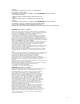
DECT 6.0 & 1.
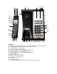
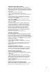
DECT Base: 1. Industrial grade construction,smooth plastic finish 2. Speaker 3. Programmable Store key 4. Programmable Flash key (100ms to 1000ms timed line break) 5. Line Cord receptacle (top end of phone) 6a. HSIA(High Speed Internet Access) receptacle incoming from wall (top end of phone) 6b. PassPort○ R HSIA(High Speed Internet Access) receptacle outgoing to guest laptop 7. Faceplate & Plastic Overlay display area (full-length,4-color printing possible) 8.
1 2 3 4 5 6a 24 25 26 6b 7 27 28 29 8 30 9 31 11 32a 33 10a 10b 32b 34 36 35 36 22 23 20 19 21 18 17 16a 16b 15 14 13 12 Handset: 24. Cordless Handset –Handset can be synchronized with base with a few simple steps 25. Message Waiting Indicator,blinks when message is waiting 26. ADA Compliant Handset Speaker 27. Handset Faceplate & Plastic Overlay 28. Line Selector key – Line 2 On/Off with LED indication 29. Hold/Conf.Handset key,and remote release 30.
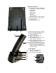
Telephone Underside: 37. Base underside sticker information: Certification – FCC,CE,ETL,ROHS Version label Model name REN number Disposal label QC label Series number Warranty Void If Seal Broken label 38. Message Waiting selector switch TYPE LR1 LR2 39. Non-Slip rubber feet (4) 39 37 40 38 Cordless Handset Charging Station: 40. Message Waiting indication 41. Cordless Handset 42. Handset Pop-Off Cover for Battery compartment 43. Interchangeable Accent Piece,to match custom cradle color 44.
Cetis DCT9602 Auto Sync SERIES USERS GUIDE DECT6.0&1.
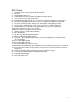
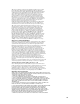
PREPARING TO USE THE 9602 SERIES 1. Prepare to install the battery into the cordless handset by Opening cover with small screwdriver.grip handset and depress Cover at hinged end.slide cover off,exposing battery compartment. 2. Slide battery plug into receptacle,matching up slot and opening On receptacle. 3. Slide battery into battery compartment. 4. Press on back end of battery to snap into place. 5. Place hinged end of cover into slot,then press down and snap into place. 6.
specific base. To accomplish this procedure, place the handset on the base in the charging position. This process occurs each time the handset is placed on the base in the charging cradle. PLACING A CALL Using the handset: 1. Pick up the handset and select either line 1 or line 2. Listen for dial tone and dial the desired number. 2. After the call is complete, press the key for the selected line again to end the call. Using the speakerphone: 1. Press key for either line 1 or line 2, or press SPKR. 2.
REDIAL The 9602 series can automatically redial the last number dialed. Off-hook, press the REDIAL key to redial the last number. USING THE HOLD KEY The HOLD key places the call on hold locally at the cordless telephone. 1. With a call active, press the HOLD key on either the To remove a call from hold: 1. Press the line key of the call on hold. This will remove the call from hold, making the call active again. 2. The red LED will return to steady illumination, indicating the line is active.
as above. 2. Using the second line, place call to second party.then place them on hold as above. 3. Activate the 3-way conference call by pressing HOLD/CONF key on the handset. User includes two callers: 1. After receiving a call from first party, place them on hold as above. 2. After receiving call from second party, place them on hold as above. 3. Activate the 3-way conference call by pressing HOLD/CONF key on the handset.
SAR: Tests for SAR are conducted using standard operating positions specified by the FCC with the UPCS handset transmitting at its highest certified power level in all tested frequency bands. Although the SAR is determined at the highest certified power level, the actual SAR level of the UPCS handset while operation can be well below the maximum value. In general, the closer you are to a wireless base station antenna, the lower the power output.
SLOTS AS THEY MAY TOUCH DANGEROUS VOLTAGE POINTS OR SHORT OUT PARTS THAT COULD RESULT IN A RISK OF FIRE OR ELECTRIC SHOCK. NEVER SPILL LIQUID OF ANY KIND ON THE PRODUCT. 8. TO REDUCE THE RISK OF ELECTRIC SHOCK DO NOT DISASSEMBLE THIS PRODUCT. BUT TAKE IT TO A QUALIFIED SERVICE FACILITY IF SERVICE OR REPAIR WORK IS REQUIRED. OPENING OR REMOVING COVERS MAY EXPOSE YOU TO DANGEROUS VOLTAGES OR OTHER RISKS. INCORRECT REASSEMBLY CAN CAUSE ELECTRIC SHOCK WHEN THE APPLIANCE IS SUBSEQUENTLY USED. 9.