M200EU-NOy CONVERTER ADDENDUM (for use with M200E Operators Manual, PN 04410 and with the M200EU Addendum, PN 05385) © TELEDYNE ADVANCED POLLUTION INSTRUMENTATION 9480 CARROLL PARK DRIVE SAN DIEGO, CA 92121-5201 USA Toll-free Phone: Phone: Fax: Email: Website: Copyright 2009-2010 Teledyne Advanced Pollution Instrumentation 800-324-5190 858-657-9800 858-657-9816 api-sales@teledyne.com http://www.teledyne-api.
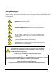
Safety Messages Important safety messages are provided throughout this manual for the purpose of avoiding personal injury or instrument damage. Please read these messages carefully. Each safety message is associated with a safety alert symbol, and are placed throughout this manual and inside the instrument. The symbols with messages are defined as follows: WARNING: Electrical Shock Hazard HAZARD: Strong oxidizer GENERAL WARNING/CAUTION: Read the accompanying message for specific information.
ii 05386 Rev.
Table of Contents Safety Messages ...................................................................................................................................... i Table of Contents................................................................................................................................... iii List of Figures ........................................................................................................................................ iv List of Tables..................
.0 M200EU-NOY SPARE PARTS LIST ...................................................................... 37 List of Figures FIGURE 1 FIGURE 2 FIGURE 3 FIGURE 4 FIGURE 5 FIGURE 6 REAR PANEL PNEUMATIC CONNECTIONS ................................................................................ 8 REPLACING THE PARTICULATE FILTER ................................................................................. 21 NOY CONVERTER ASSEMBLY .............................................................................
1.0 INTRODUCTION The M200EU-NOy converter is designed to support a NOx analyzer by converting multiple, unstable compounds grouped under the name NOy. The converter is mounted on the analyzer at the sample inlet to minimize flow time between sample in and converter, thereby optimizing measurement accuracy. This manual addendum is to be used in conjunction with the M200E operation manual and the M200EU addendum. 05386 Rev.
Model 200EU-NOy Option Manual Addendum This page intentionally left blank. 6 05386 Rev.
2.0 GETTING STARTED The NOy converter has been designed to operate with the M200EU low level NOx analyzer. 2.1 Unpacking CAUTION! Avoid personal injury: use two persons each to lift and carry the the M200EU analyzer and the Model 501 Pump Pack chassis. The M200EU with NOy Option comes in three boxes: M200EU analyzer Bypass Pump Chassis External Converter housed in a stainless enclosure, and umbilical cable assembly 1. Verify that there is no apparent shipping damage.
Model 200EU-NOy Option Manual Addendum Figure 1 Rear Panel Pneumatic Connections 8 05386 Rev.
Model 200EU-NOy Option Manual Addendum 2.3 Initial Operation 1. After confirming proper supply voltage, turn on the instrument power. If you are unfamiliar with the M200EU with NOy Option, we recommend that you read the overview in Section 3 before proceeding. The power indicator light and display should immediately light, in addition the bypass pump should start up. The Bypass Pump Chassis requires about 30 minutes for the converter to come up to temperature.
Model 200EU-NOy Option Manual Addendum This page intentionally left blank. 10 05386 Rev.
3.0 SPECIFICATIONS, WARRANTY 3.1 Specifications Table 2. Specifications for the converter and the Bypass Pump Remotely mounted molybdenum converter with temperature controller in a NEMA – 4 enclosure. Converter Temperature 315oC 7oC with read-out on front panel of bypass pump chassis.
Model 200EU-NOy Option Manual Addendum 3.2 Warranty TELEDYNE ADVANCED POLLUTION INSTRUMENTATION, INC. 02024c Prior to shipment, API equipment is thoroughly inspected and tested. Should equipment failure occur, API assures its customers that prompt service and support will be available. COVERAGE After the warranty period and throughout the equipment lifetime, API stands ready to provide on-site or inplant service at reasonable rates similar to those of other manufacturers in the industry.
4.0 THE M200EU-NOY CONVERTER 4.1 Principle of Operation The T-API Model M200EU with NOy Option is designed to measure the concentration of NO, NO2, and other compounds that are too unstable to be measured when taken in through the normal ambient air sample inlet system. Please refer to the M200EU manual supplied with this system for a general discussion of the operation of a NOx analyzer. The suite of compounds known collectively as NOy is composed of roughly 30 compounds.
Model 200EU-NOy Option Manual Addendum This page intentionally left blank. 14 05386 Rev.
5.0 CALIBRATION AND ZERO/SPAN CHECKS Unlike most NOx analyzers, the M200EU with the NOy option does not have a sample inlet port on the rear panel of the M200EU. The sample port is located on the External Converter; therefore Zero/Span calibration is different than a normal NOx instrument. If a fitting is located at the sample port the analyzer is equipped with the Zero/Span option. Follow the steps in the M200E/EU manual to: a. Enter the expected NO and NOy span gas concentrations in the M200EU. b.
Model 200EU-NOy Option Manual Addendum NOTE The M200EU with the NOy Option does NOT have equivalency approval, and may not be used for EPA monitoring. 5.1 Calibration or Cal Check Procedure The calibration of the instrument can be checked or adjusted using gas introduced through the calibration port “CAL IN” on the Bypass Pump Module. The calibration gas is routed to a TEE near the sample inlet port on the remote converter assembly.
Model 200EU-NOy Option Manual Addendum Table 4 Enter Expected Span Gas Concentrations Procedure For NO & NOy Step Action Comment 1. Press CAL-CONC-NOy This key sequence causes the M200EU to prompt for the expected NOy concentration. Enter the NOy span concentration value by pressing the key under each digit until the expected value is set. 2. Press ENTR ENTR stores the expected NOy span value. 3. Press CAL-CONC-NO Now enter the expected NO span concentration as in step one. 4. Press ENTR 5.
Model 200EU-NOy Option Manual Addendum This page intentionally left blank. 18 05386 Rev.
6.0 MAINTENANCE 6.1 Maintenance Schedule The schedule for preventative maintenance is presented in Table 6 below.
Model 200EU-NOy Option Manual Addendum 6.2 Replacing the Sample Particulate Filters The particulate filter should be inspected often for signs of plugging or contamination. It is also common for dirt particles to cause instrument drift, and affect accuracy. To check and change the filter: 1. Fold down the Bypass Pump Module front panel. 2. Locate both filters on the left and right side of the Pump Module front panel. See Figure 2 for an exploded view of the filter assembly. 3.
Model 200EU-NOy Option Manual Addendum Figure 2 Replacing the Particulate Filter 05386 Rev.
Model 200EU-NOy Option Manual Addendum 6.3 Checking Analyzer Flow Rate The external sample pump is capable of maintaining the reaction cell pressure at less than 5.0 In-Hg-A. If a higher pressure is noted, the pump may need servicing. Check the pump and pneumatic system for leaks or rebuild pump. CAUTION! Never operate the analyzer without the ozone destruct component properly seated and connected within the pneumatic path.
Model 200EU-NOy Option Manual Addendum NOy Out NO Out Sample In Figure 3 NOy Converter Assembly 05386 Rev.
Model 200EU-NOy Option Manual Addendum 6.5 Inspecting Pneumatic Lines Particulate matter in the pneumatic lines will affect both flow rate and response time. It is important that the pneumatic system be periodically inspected and thoroughly cleaned if necessary. Clean by disassembling and passing methanol through three times. Dry with clean zero air. Also inspect all pneumatic lines for cracks and abrasion on a regular basis. necessary. 24 Replace as 05386 Rev.
Model 200EU-NOy Option Manual Addendum Figure 4 Pneumatics diagram (standard and Z/S option) 05386 Rev.
Model 200EU-NOy Option Manual Addendum Figure 5 Pneumatic diagram (OPT 86 option – Sample Driers) 26 05386 Rev.
Model 200EU-NOy Option Manual Addendum 6.6 Checking for Leaks If a leak checker is not available, it is possible to leak check the instrument using the sample pump plus a shut-off valve. 1. 2. 3. 4. Turn off instrument power and pump power. Cap the sample inlet port, bypass out port, ozone generator air inlet, and zero/span inlets (if Z/S valve option present). Insert a shut-off valve between the sample pump and the exhaust port at the rear of the instrument. Turn on instrument and sample pump power.
Model 200EU-NOy Option Manual Addendum This page intentionally left blank. 28 05386 Rev.
7.0 TROUBLESHOOTING, ADJUSTMENTS CAUTION! The operations outlined in this section must be performed by qualified maintenance personnel only! This section of the manual contains information on diagnosing and repairing instrument performance problems. It provides troubleshooting procedures that address problems to the board level. As a guide to troubleshooting, think of the M200EU-NOy as two systems: Pneumatics and Electronics.
Model 200EU-NOy Option Manual Addendum 7.1 Operation Verification – Diagnostic Techniques 7.1.1 Pneumatic System 30 05386 Rev.
Model 200EU-NOy Option Manual Addendum The pneumatic system is diagramed in 05386 Rev.
Model 200EU-NOy Option Manual Addendum Figure 4. 7.1.2 Leak Check Refer to Section 5.6 for the leak check procedure. 7.1.3 Bypass Pump Diagnostic Procedures The bypass pump is capable of maintaining a total bypass flowrate of ~2.2 lpm. If flow checks indicate a fall off in bypass flow, the pump may need servicing. Check the pump, inlet fittings, and analyzer for leaks first. If other causes have been eliminated, rebuild the pump. 7.1.
Model 200EU-NOy Option Manual Addendum Indications that would require re-programming are: Failure / replacement of controller. Replacement of thermocouple element. Controller’s loss of PID parameters leading to instability of the temp setpoint. In the event that the control parameters are changed or in the event that a new controller is installed, it must be reprogrammed to suit the thermal characteristics of the instrument.
Model 200EU-NOy Option Manual Addendum SECONDARY MENU (The fixed characteristics of the system).
Model 200EU-NOy Option Manual Addendum Figure 6 Electrical Diagram 05386 Rev.
Model 200EU-NOy Option Manual Addendum This page intentionally left blank. 36 05386 Rev.
8.0 M200EU-NOY SPARE PARTS LIST The following spare parts list supplements the spare parts list for the M200EU analzyer. Note: Use of replacement parts other than those supplied by API may result in noncompliance with European Standard EN 61010-1. PART NO. 000940400 000941000 016300300 047200200 023180000 009690200 009690300 PS0000038 PS0000037 FA0000006 013140000 FL0000001 FL0000003 052900300 HW0000020 HW0000036 HW0000037 OR0000094 037860000 OR0000086 PU0000005 PU0000011 046150000 055300000 05386 Rev.