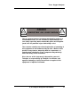
Trace Oxygen Analyzer OPERATING INSTRUCTIONS FOR Model 3000TB Trace Oxygen Analyzer DANGER HIGHLY TOXIC AND OR FLAMMABLE LIQUIDS OR GASES MAY BE PRESENT IN THIS MONITORING SYSTEM. PERSONAL PROTECTIVE EQUIPMENT MAY BE REQUIRED WHEN SERVICING THIS SYSTEM. HAZARDOUS VOLTAGES EXIST ON CERTAIN COMPONENTS INTERNALLY WHICH MAY PERSIST FOR A TIME EVEN AFTER THE POWER IS TURNED OFF AND DISCONNECTED. ONLY AUTHORIZED PERSONNEL SHOULD CONDUCT MAINTENANCE AND/OR SERVICING.
Model 3000TB Copyright © 2010 Teledyne Analytical Instruments All Rights Reserved. No part of this manual may be reproduced, transmitted, transcribed, stored in a retrieval system, or translated into any other language or computer language in whole or in part, in any form or by any means, whether it be electronic, mechanical, magnetic, optical, manual, or otherwise, without the prior written consent of Teledyne Analytical Instruments, 16830 Chestnut Street, City of Industry, CA 91749-1580.
Trace Oxygen Analyzer Model 3000TB complies with all of the requirements of the Commonwealth of Europe (CE) for Radio Frequency Interference, Electromagnetic Interference (RFI/EMI), and Low Voltage Directive (LVD).
Model 3000TB Table of Contents 1 Introduction 1.1 Overview ........................................................................ 1-1 1.2 Typical Applications ....................................................... 1-1 1.3 Main Features of the Analyzer ....................................... 1-1 1.4 Model Designations ....................................................... 1-2 1.5 Operator Interface .......................................................... 1-3 1.5.1 Displays ............................
Trace Oxygen Analyzer 3.4 Installing the Micro-Fuel Cell ......................................... 3-12 3.5 Gas Connections ........................................................... 3-12 3.6 Testing the System ......................................................... 3-14 4 Operation 4.1 Introduction .................................................................... 4-1 4.2 Using the Data Entry and Function Buttons ................... 4-2 4.3 The System Function ........................................
Model 3000TB 5.4 Fuse Replacement......................................................... 5-7 5.5 System Self Diagnostic Test ........................................... 5-7 5.6 Troubleshooting ............................................................. 5-9 Appendix A-1 A-2 A-3 A-5 vi Specifications ................................................................ A-1 Recommended 2-Year Spare Parts List ......................... A-2 Drawing List .........................................................
Trace Oxygen Analyzer DANGER COMBUSTIBLE GAS USAGE WARNING This is a general purpose instrument designed for usage in a nonhazardous area. It is the customer's responsibility to ensure safety especially when combustible gases are being analyzed since the potential of gas leaks always exist. The customer should ensure that the principles of operating of this equipment is well understood by the user.
Model 3000TB Specific Model Information The instrument for which this manual was supplied may incorporate one or more options not supplied in the standard instrument. Commonly available options are listed below, with check boxes. Any that are incorporated in the instrument for which this manual is supplied are indicated by a check mark in the box.
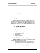
Trace Oxygen Analyzer Introduction 1 Introduction 1.1 Overview The Teledyne Analytical Instruments Model 3000TB Trace Oxygen Analyzer is a versatile microprocessor-based instrument for detecting oxygen in a variety of gases. This manual covers the Model 3000TB, trace oxygen, bulkhead-mount, general purpose units only. These instruments are for use in nohazardous environments only. 1.
1 Introduction Model 3000TB • 316 Stainless steel cell block and sample system—all wetted parts. • Advanced Micro-Fuel Cell for trace analysis. Standard cell has a six month warranty and an expected lifetime of eight months. • Versatile analysis over a wide range of applications. • Microprocessor based electronics: 8-bit CMOS microprocessor with 32 kB RAM and 128 kB ROM. • Three user definable output ranges (from 0-10 ppm through 025 % allow best match to users process and equipment.
Trace Oxygen Analyzer 1.5 Introduction 1 Operator Interface Figure 1-1 is an illustration of the front of the Model 3000TB Oxygen Analyzer with the outer door open showing the control panel (which is also the inner door). All displays on the standard 3000TB are visible from outside the housing.
1 Introduction Model 3000TB (Pressing the latch button will open the Inner Door) Figure 1-1: Model 3000TB—Outer Door Open—Showing Control Panel 1-4 Teledyne Analytical Instruments
Trace Oxygen Analyzer Introduction 1 Figure 1-2: Model 3000TB—Inner Door Open—Showing Internal Components Teledyne Analytical Instruments 1-5
1 Introduction Model 3000TB 1.5.1 Displays Digital Meter Display: The meter display is a LED device that produces large, bright, 7-segment numbers that are legible in any lighting environment. It produces a continuous readout from 0-9999 ppm and from 125 %. It is accurate across all ranges without the discontinuity of analog range switching. Alphanumeric Interface Screen: The backlit VFD screen is an easyto-use interface from operator to analyzer.
Trace Oxygen Analyzer • Introduction 1 Escape Moves VFD display back to the previous screen in a series. If none remains, returns to the Analyze screen. 1.5.4 I/O Power Button The red I/O button switches the instrument power between I (ON) and O (a Keep-Alive state). In the O state, the instrument’s circuitry is operating, but there are no displays or outputs. CAUTION: The power cable must be unplugged to fully disconnect power from the instrument.
1 Introduction Model 3000TB 3.0 A MAX Figure 1-3: Electrical Connector Panel Electrical Connections: The electrical connections on the electrical connector panel are described briefly here, and in more detail in chapter 3 Installation. 1-8 • Power Connection 115 or 230 V dc, 50 or 60 Hz. • Analog Outputs 0-1 V dc concentration plus 0-1 V dc range ID, and isolated 4-20 mA dc plus 4-20 mA dc range ID. • Alarm Connections 2 concentration alarms and 1 system alarm.
Trace Oxygen Analyzer Introduction 1 • RS-232 Port Serial digital concentration signal output and control input. • Remote Valves Used for controlling external solenoid valves, if desired. • Remote Sensor Used for external sensor and thermocouple, if desired. • Remote Span/Zero Digital inputs allow external control of analyzer calibration. • Calibration Contact To notify external equipment that instrument is being calibrated and readings are not monitoring sample.
1 Introduction • Model 3000TB Gas Inlet and Outlet One inlet (must be externally valved) and one exhaust out. Optional: • Calibration Gas Ports Separate fittings for zero, span and sample gas input, plus internal valves for automatically switching the gases in sync with the 3000TB electronics. Note: If you require highly accurate Auto-Cal timing, use external Auto-Cal control where possible. The internal clock in the Model 3000TB is accurate to 2-3 %.
Trace Oxygen Analyzer Operational Theory 2 Operational Theory 2.1 Introduction The analyzer is composed of three subsystems: 1. Micro-Fuel Cell Sensor 2. Sample System 3. Electronic Signal Processing, Display and Control The sample system is designed to accept the sample gas and transport it through the analyzer without contaminating or altering the sample prior to analysis.
2 Operational Theory Model 3000TB analyzed. The Micro-Fuel Cell is therefore a hybrid between a battery and a true fuel cell. (All of the reactants are stored externally in a true fuel cell.) 2.2.2 Anatomy of a Micro-Fuel Cell The Micro-Fuel Cell is a cylinder only 1¼ inches in diameter and 1¼ inches thick. It is made of an extremely inert plastic, which can be placed confidently in practically any environment or sample stream.
Trace Oxygen Analyzer Operational Theory 2 At the top end of the cell is a diffusion membrane of Teflon, whose thickness is very accurately controlled. Beneath the diffusion membrane lies the oxygen sensing element—the cathode—with a surface area almost 4 cm2. The cathode has many perforations to ensure sufficient wetting of the upper surface with electrolyte, and it is plated with an inert metal. The anode structure is below the cathode.
2 Operational Theory Model 3000TB The overall reaction for the fuel cell is the SUM of the half reactions above, or: 2Pb + O2 → 2PbO (These reactions will hold as long as no gaseous components capable of oxidizing lead—such as iodine, bromine, chlorine and fluorine—are present in the sample.) The output of the fuel cell is limited by (1) the amount of oxygen in the cell at the time and (2) the amount of stored anode material. In the absence of oxygen, no current is generated. 2.2.
Trace Oxygen Analyzer Operational Theory 2 Figure 2-3. Characteristic Input/Output Curve for a Micro-Fuel Cell 2.3 Sample System The sample system delivers gases to the Micro-Fuel Cell sensor from the analyzer gas panel inlets. Depending on the mode of operation either sample or calibration gas is delivered. The Model 3000TB sample system is designed and fabricated to ensure that the oxygen concentration of the gas is not altered as it travels through the sample system.
2 Operational Theory Model 3000TB Figure 2-4 is the flow diagram for the sampling system. In the standard instrument, calibration gases (zero and span) can be connected directly to the Sample In port by teeing to the port with appropriate valves. The shaded portion of the diagram shows the components added when the –C option is ordered. The valves, when supplied, are installed inside the 3000TB enclosure and are regulated by the instruments internal electronics.
Trace Oxygen Analyzer Operational Theory 2 Figure 2-5: Block Diagram of the Model 3000TB Electronics Teledyne Analytical Instruments 2-7
2 Operational Theory Model 3000TB In the presence of oxygen the cell generates a current. A current to voltage amplifier converts this current to a voltage, which is amplified in the second stage amplifier. The second stage amplifier also supplies temperature compensation for the oxygen sensor output. This amplifier circuit incorporates a thermistor, which is physically located in the cell block.
Trace Oxygen Analyzer Installation 3 Installation Installation of the Model 3000TB Analyzer includes: 1. Unpacking 2. Mounting 3. Gas connections 4. Electrical connections 5. Installing the Micro-Fuel Cell 6. Testing the system. 3.1 Unpacking the Analyzer The analyzer is shipped with all the materials you need to install and prepare the system for operation. Carefully unpack the analyzer and inspect it for damage. Immediately report any damage to the shipping agent. 3.
3 Installation Model 3000TB Figure 3-1: Front View of the Model 3000TB (Simplified) 3-2 Teledyne Analytical Instruments
Trace Oxygen Analyzer Installation 3 Figure 3-2: Required Front Door Clearance 3.3 Electrical Connections Figure 3-3 shows the Model 3000TB Electrical Connector Panel. There are terminal blocks for connecting power, communications, and both digital and analog concentration outputs.
3 Installation Model 3000TB For safe connections, ensure that no uninsulated wire extends outside of the connectors they are attached to. Stripped wire ends must insert completely into terminal blocks. No uninsulated wiring should be able to come in contact with fingers, tools or clothing during normal operation. 3.3.1 Primary Input Power The universal power supply requires a 115 or 230 V ac, 50 or 60 Hz power source.
Trace Oxygen Analyzer Installation 3 Figure 3-5: Analog Output Connections The outputs are: 0–1 V dc % of Range: Voltage rises linearly with increasing oxygen, from 0 V at 0 ppm to 1 V at full scale ppm. (Full scale = 100% of programmable range.) 0–1 V dc Range ID: 0.25 V = Low Range, 0.5 V = Medium Range, 0.75 V = High Range, 1 V = Air Cal Range. 4–20 mA dc % Range: Current increases linearly with increasing oxygen, from 4 mA at 0 ppm to 20 mA at full scale ppm.
3 Installation Model 3000TB Table 3-1: Analog Concentration Output—Example ppm O2 Voltage Signal Output (V dc) 0 10 20 30 40 50 60 70 80 90 100 0.0 0.1 0.2 0.3 0.4 0.5 0.6 0.7 0.8 0.9 1.0 Current Signal Output (mA dc) 4.0 5.6 7.2 8.8 10.4 12.0 13.6 15.2 16.8 18.4 20.0 To provide an indication of the range, a second pair of analog output terminals are used. They generate a steady preset voltage (or current when using the current outputs) to represent a particular range.
Trace Oxygen Analyzer Installation 3 Figure 3-6: Types of Relay Contacts The connectors are: Threshold Alarm 1: • Can be configured as high (actuates when concentration is above threshold), or low (actuates when concentration is below threshold). • Can be configured as failsafe or nonfailsafe. • Can be configured as latching or nonlatching. • Can be configured out (defeated).
3 Installation Model 3000TB ZERO: Floating input. 5 to 24 V input across the + and – terminals puts the analyzer into the Zero mode. Either side may be grounded at the source of the signal. 0 to 1 volt across the terminals allows Zero mode to terminate when done. A synchronous signal must open and close the external zero valve appropriately. See section 3.3.9 Remote Sensor and Solenoid Valves. (With the –C option, the internal valves automatically operate synchronously.) SPAN: Floating input.
Trace Oxygen Analyzer Installation 3 Note: The remote probe connections (paragraph 3.3.9) provides signals to ensure that the zero and span gas valves will be controlled synchronously. If you have the –C Internal valve option—which includes additional zero and span gas inputs— the 3000TB automatically regulates the zero, span and sample gas flow. 3.3.6 Range ID Relays There are four dedicated RANGE ID CONTACT relays.
3 Installation • • • • Model 3000TB The range in use (HI, MED, LO) The span of the range (0-100 ppm, etc) Which alarms—if any—are disabled (AL–x DISABLED) Which alarms—if any—are tripped (AL–x ON). Each status output is followed by a carriage return and line feed. Three input functions using RS-232 have been implemented to date. They are described in Table 3-4. Table 3-4: Commands via RS-232 Input Command Description as Immediately starts an autospan.
Trace Oxygen Analyzer Installation 3 Figure 3-7: Remote Sensor Connector Pinouts Figure 3-8: Remote Solenoid Return Connector Pinouts The voltage from these outputs is nominally 0 V for the OFF and 15 V dc for the ON conditions. The maximum combined current that can be pulled from these output lines is 100 mA. (If two lines are ON at the same time, each must be limited to 50 mA, etc.
3 Installation 3.4 Model 3000TB Installing the Micro-Fuel Cell The Micro-Fuel Cell is not installed in the cell block when the instrument is shipped. It must be installed before the analyzer is placed in service. Once it is expended, or if the cell is exposed to air for too long, the Micro-Fuel Cell will need to be replaced. The cell could also require replacement if the instrument has been idle for too long.
Trace Oxygen Analyzer Installation 3 2. Hold the fitting body steady with a backup wrench, and with another wrench rotate the nut another 11/4 turns. Figure 3-10: Gas Connector Panel SAMPLE IN: In the standard model, gas connections are made at the SAMPLE IN and EXHAUST OUT connections. Calibration gases must be Tee'd into the Sample inlet with appropriate valves. The gas pressure in should be reasonably regulated.
3 Installation Model 3000TB EXHAUST OUT: Exhaust connections must be consistent with the hazard level of the constituent gases. Check Local, State, and Federal laws, and ensure that the exhaust stream vents to an appropriately controlled area if required. Note: If the unit is for vacuum service, see Sample In, above, for gas pressure/flow considerations. 3.6 Testing the System Before plugging the instrument into the power source: • Check the integrity and accuracy of the gas connections.
Trace Oxygen Analyzer Operation 4 Operation 4.1 Introduction Once the analyzer has been installed, it can be configured for your application. To do this you will: • • • • Set system parameters: • Establish a security password, if desired, requiring Operator to log in. • Establish and start an automatic calibration cycle, if desired. Calibrate the instrument. Define the three user selectable analysis ranges. Then choose autoranging or select a fixed range of analysis, as required.
4 Operation 4.2 Model 3000TB Using the Data Entry and Function Buttons Data Entry Buttons: The < > arrow buttons select options from the menu currently being displayed on the VFD screen. The selected option blinks. When the selected option includes a modifiable item, the Δ∇ arrow buttons can be used to increment or decrement that modifiable item. The Enter button is used to accept any new entries on the VFD screen.
Trace Oxygen Analyzer Operation 4 ANALYZE SYSTEM Perform Oxygen Analysis of the Sample SPAN TRAK/HLD ZERO Set Instrument Span Perform Self-Diagnostic Test ALARMS Set Instrument Zero Initiate Automatic Calibration RANGE Set Alarm Setpoints Confrigure Mode of Alarm Operation Set Password Define Analysis Ranges Logout Show Negative Figure 4-1: Hierarchy of Functions and Subfunctions 4.3 The System Function The subfuctions of the System function are described below.
4 Operation • • • • • • Model 3000TB After a password is assigned, the operator must log out to activate it. Until then, anyone can continue to operate the instrument without entering the new password. Only one password can be defined. Before a unique password is assigned, the system assigns TETAI by default. This allows access to anyone. After a unique password is assigned, to defeat the security, the password must be changed back to TETAI.
Trace Oxygen Analyzer Operation 4 In the first line, TRACK or HOLD should be blinking. The operator can toggle between TRACK and HOLD with the Up or Down keys. When TRACK is selected, the analog outputs (0-1 VDC and 4-20 ma) and the range ID contacts will track the instrument readings during calibration (either zero or span). TRACK is the factory default.
4 Operation Model 3000TB Use < > arrows to blink Auto—Cal, and press Enter. A new screen for Span/Zero set appears. Span OFF Nxt: 0d 0h Zero OFF Nxt: 0d 0h Press < > arrows to blink Span (or Zero), then press Enter again. (You won’t be able to set OFF to ON if a zero interval is entered.) A Span Every ... (or Zero Every ...) screen appears. Span Every 0 d Start 0 h from now Use Δ∇ arrows to set an interval value, then use < > arrows to move to the start-time value.
Trace Oxygen Analyzer Operation 4 Press System to enter the System mode. TRAK/HLD Auto—Cal PSWD Logout More Use the < > arrow keys to scroll the blinking over to PSWD, and press Enter to select the password function. Either the default TETAI password or AAAAA place holders for an existing password will appear on screen depending on whether or not a password has been previously installed. TETAI Enter PWD or AAAAA Enter PWD The screen prompts you to enter the current password.
4 Operation Model 3000TB Press Enter to change the password (either the default TETAI or the previously assigned password), or press Escape to keep the existing password and move on. If you chose Enter to change the password, the password assignment screen appears. TETAI To Proceed or AAAAA To Proceed Enter the password using the < > arrow keys to move back and forth between the existing password letters, and the Δ∇ arrow keys to change the letters to the new password.
Trace Oxygen Analyzer Operation 4 will immediately switch to the Analyze screen, and you now have access to all instrument functions. If all alarms are defeated, the Analyze screen appears as: 0.0 ppm Anlz Range: 0 — 100 If an alarm is tripped, the second line will change to show which alarm it is: 0.0 ppm Anlz AL—1 NOTE:If you log off the system using the logout function in the system menu, you will now be required to re-enter the password to gain access to Span, Zero, Alarm, and Range functions. 4.3.
4 Operation Model 3000TB The self diagnostics are run automatically by the analyzer whenever the instrument is turned on, but the test can also be run by the operator at will. To initiate a self diagnostic test during operation: Press the System button to start the System function. TRAK/HLD Auto—Cal PSWD Logout More Use the < > arrow keys to blink More, then press Enter. Version Self—Test Use the < > arrow keys again to move the blinking to the Self–Test function.
Trace Oxygen Analyzer Operation 4 To show negative oxygen readings on the display: - Press the System key TRAK/HLD Auto-Cal PSWD Logout More - Use the Right or Left arrow keys and select More. Press Enter. Version Self-Test Show_Negative=NO - Use the Right or Left arrow keys and select “Show_Negative=NO”. - Use the Up or Down key to toggle from NO to YES. - Press the Escape key twice to return to the analyze mode.
4 Operation Model 3000TB Shut off the gas pressure before connecting it to the analyzer, and be sure to limit the pressure to 40 psig or less when turning it back on. Readjust the gas pressure into the analyzer until the flowrate (as read on the analyzer’s SLPM flowmeter) settles between 0.5 and 2.4 SLPM (approximately 1-5 scfh). If you are using password protection, you will need to enter your password to gain access to either of these functions. Follow the instructions in sections 4.3.
Trace Oxygen Analyzer Operation 4 #### 4 Left=### PPM Zero ppm/s The zeroing process will automatically conclude when the output is within the acceptable range for a good zero. Then the analyzer automatically returns to the Analyze mode. 4.4.1.2 Manual Mode Zeroing Press Zero to enter the Zero function. The screen that appears allows you to select between automatic or manual zero calibration. Use the Δ∇ keys to toggle between AUTO and MAN zero settling. Stop when MAN appears, blinking, on the display.
4 Operation Model 3000TB CELL FAIL/ ZERO HIGH Before replacing the cell: a. Check your span gas to make sure it is within specifications. b. Check for leaks downstream from the cell, where oxygen may be leaking into the system. If there are no leaks and the span gas is OK, replace the cell as described in chapter 5, Maintenance. 4.4.2 Span Cal The Span button on the front panel is used to span calibrate the analyzer.
Trace Oxygen Analyzer Operation 4 Use the Δ∇ arrow keys to enter the oxygen-concentration mode. Use the < > arrow keys to blink the digit you are going to modify. Use the Δ∇ arrow keys again to change the value of the selected digit. When you have finished typing in the concentration of the span gas you are using (209000.00 if you are using air), press Enter to begin the Span calibration. #### ppm Slope=#### Span ppm/s The beginning span value is shown in the upper left corner of the display.
4 Operation Model 3000TB Once the span has begun, the microprocessor samples the output at a predetermined rate. It calculates the difference between successive samplings and displays this difference as Slope on the screen. It takes several seconds for the first Slope value to display. Slope indicates rate of change of the Span reading. It is a sensitive indicator of stability. #### % Span Slope=#### ppm/s When the Span value displayed on the screen is sufficiently stable, press Enter.
Trace Oxygen Analyzer Operation 4 Chapter 3, Installation and/or the Interconnection Diagram included at the back of this manual for relay terminal connections. The system failure alarm has a fixed configuration described in chapter 3 Installation. The concentration alarms can be configured from the front panel as either high or low alarms by the operator. The alarm modes can be set as latching or non-latching, and either failsafe or non-failsafe, or, they can be defeated altogether.
4 Operation Model 3000TB If you are using password protection, you will need to enter your password to access the alarm functions. Follow the instructions in section 4.3.3 to enter your password. Once you have clearance to proceed, enter the Alarm function. Press the Alarm button on the front panel to enter the Alarm function. Make sure that AL–1 is blinking. AL—1 AL—2 Choose Alarm Set up alarm 1 by moving the blinking over to AL–1 using the < > arrow keys. Then press Enter to move to the next screen.
Trace Oxygen Analyzer 4.6 Operation 4 The Range Function The Range function allows the operator to program up to three concentration ranges to correlate with the DC analog outputs. If no ranges are defined by the user, the instrument defaults to: Low = 0–100 ppm Med = 0–1,000 ppm High = 0–10,000 ppm. The Model 3000TB is set at the factory to default to autoranging. In this mode, the microprocessor automatically responds to concentration changes by switching ranges for optimum readout sensitivity.
4 Operation Model 3000TB Note: The ranges must be increasing from low to high, for example, if range 1 is set as 0–100 ppm and range 2 is set as 0–1,000 ppm, range 3 cannot be set as 0– 500 ppm since it is lower than range 2. Ranges, alarms, and spans are always set in ppm units (over the entire 0-250,000 ppm range), even though all concentration-data outputs change from ppm units to percent when the concentration is above 10,000 ppm. 4.6.
Trace Oxygen Analyzer 4.7 Operation 4 The Analyze Function This is the normal operating mode of the analyzer. In this Mode the analyzer is monitoring the sample, measuring and displaying the amount of oxygen, and reporting alarm conditions. Normally, all of the functions automatically switch back to the Analyze function when they have completed their assigned operations. Pressing the Escape button in many cases also switches the analyzer back to the Analyze function.
4 Operation 4-22 Model 3000TB Teledyne Analytical Instruments
Trace Oxygen Analyzer Maintenance 5 Maintenance 5.1 Routine Maintenance Aside from normal cleaning and checking for leaks at the gas connections, routine maintenance is limited to replacing Micro-Fuel cells and fuses, and recalibration. For recalibration, see Section 4.4 The Zero and Span Functions. WARNING: SEE WARNINGS ON TITLE PAGE OF THIS MANUAL. 5.2 Major Internal Components All internal components are accessed by unlatching and swinging open the front cover, as described earlier.
5 Maintenance Model 3000TB Figure 5-1: Major Internal Components 5.3 Cell Replacement The Micro-Fuel Cell is a sealed electrochemical transducer with no electrolyte to change or electrodes to clean. When the cell reaches the end of its useful life, it is replaced. The spent fuel cell should be discarded in accordance with to all applicable safety and environmental regulations. This section describes fuel cell care as well as when and how to replace it.
Trace Oxygen Analyzer Maintenance 5 5.3.1 Storing and Handling Replacement Cells To have a replacement cell available when it is needed, it is recommended that one spare cell be purchased 9-10 months after commissioning the 3000TB, or shortly before the end of the cell's one year warranty period. CAUTION: Do not stockpile cells. The warranty period starts on the day of shipment.
5 Maintenance Model 3000TB a. Check your span gas to make sure it is within specifications. b. Check for leaks downstream from the cell, where oxygen may be leaking into the system. If there are no leaks and the span gas is OK, replace the cell. The only way to avoid all fail messages is to turn unit off and on. 5.3.3 Removing the Micro-Fuel Cell The Micro-Fuel Cell is located inside the stainless steel cell block behind the inner door (see Figure 5-1). To remove an existing cell: 1.
Trace Oxygen Analyzer Maintenance 5 Lift Up Gate Cell Block Outer and inner doors removed for clarity Micro-Fuel Cell Cell Adaptor (For B-2 or A-2 series cell) O-Ring Cell Holder Figure 5-2: Exploded View of Cell Block and Micro-Fuel Cell Teledyne Analytical Instruments 5-5
5 Maintenance Model 3000TB 5.3.4 Installing a New Micro-Fuel Cell It is important to minimize the amount of time that a Teledyne Trace Oxygen Sensor is exposed to air during the installation process. The quicker the sensor can be installed into the unit, the faster your TAI O2 sensor will recover to low O2 measurement levels. CAUTION: Do not touch the sensing surface of the cell. It is covered with a delicate Teflon membrane that can leak when punctured.
Trace Oxygen Analyzer Maintenance 5 5.3.5 Cell Warranty The Class L-2C Micro-Fuel cell is used in the Model 3000TB. This cell is a long life cell and is warranted for 1 year from the date of shipment. If any other cell is supplied with your instrument, check the front of this manual for any special information applying to your cell. With regard to spare cells, warranty period begins on the date of shipment. The customer should purchase only one spare cell (per section 5.3.1).
5 Maintenance Model 3000TB 3.0 A MAX Figure 5-3: Removing Fuse Cap and Fuse from Holder 2. Replace fuse by reversing process in step 1. 5.5 System Self Diagnostic Test 1. From System Mode, use arrow keys to move to More, and press Enter. 2. Again use arrow keys to move to Self-Test, and press Enter. RUNNING DIAGNOSTIC Testing Preamp — 83 During preamp testing there is a countdown in the lower right corner of the screen. When the testing is complete, the results are displayed.
Trace Oxygen Analyzer Maintenance 5 Table 5-1: Self Test Failure Codes Power 0 1 2 3 OK 5 V Failure 15 V Failure Both Failed Analog 0 1 2 3 OK DAC A (0–1 V Concentration) DAC B (0–1 V Range ID) Both Failed Preamp 0 1 2 3 5.6 OK Zero too high Amplifier output doesn't match test input Both Failed Troubleshooting Problem: Erratic readings of the Oxygen concentration as reported by the analyzer. Possible Cause: The analyzer may have been calibrated in an inaccurate fashion.
5 Maintenance Model 3000TB Increase flow rate and/or length or vent tubing in order to dilute of minimize the diffusion of oxygen from the vent back to the sensor. Problem: Inaccurate zero operation (i.e. the user has zeroed the analyzer accidentally on gas much higher than one would normally use for a zero gas). Solution: Turn the analyzer off, then back on again. Press the System key when prompted by the analyzer "Press System for default Values".
Trace Oxygen Analyzer Appendix Appendix A-1 Specifications Packaging: NEMA-4, weather-proof, bulkhead mount. Sensor: L-2C trace analysis Micro-Fuel Cell, B2CXL for XL option. Cell Block: 316 stainless steel. Ranges: Three user definable ranges from 0–10 ppm to 0– 250,000 ppm, plus air calibration range of 0250,000 ppm (25 %). XL-Option Ranges: 0–1 ppm to 0–250,000 ppm, plus air calibration range of 0-250,000 ppm (25 %). Autoranging with range ID output.
Appendix Model 3000TB Accuracy: ±2% of full scale at constant temperature. ±5% of full scale over operating temperature range, on factory default analysis ranges, once thermal equilibrium has been achieved. XL-Option Accuracy: ±1 ppm on 0-10 ppm once thermal equilbrium is reached. 0-1 ppm range is +0.2 ppm once thermal equilibrium has been achieved. Analog outputs: 0-1 V dc percent-of-range 0-1 V dc range ID.
Trace Oxygen Analyzer Appendix Orders should be sent to: TELEDYNE ANALYTICAL INSTRUMENTS 16830 Chestnut Street City of Industry, CA 91749-1580 Phone (626) 934-1500, Fax (626) 961-2538 Web: www.teledyne-ai.com or your local representative. A-3 Drawing List D66674 D66675 NOTE: Outline Drawing Wiring Diagram The MSDS on this material is available upon request through the Teledyne Environmental, Health and Safety Coordinator.
Appendix Model 3000TB A-5 3000 SERIES ANALYZERS APPLICATION NOTES ON RESTRICTORS, PRESSURES, AND FLOW RECOMMENDATIONS 3000 series analyzers require reasonably regulated sample pressures. While the 3000 analyzers are not sensitive to variations of incoming pressure (provided they are properly vented to atmospheric pressure) The pressure must be maintained as to provide a useable flow rate trough the analyzer. Any line attached to sample vent should be 1/4 or larger in diameter.
Trace Oxygen Analyzer Appendix The second function that the restriction device provides is a pressure drop. This device is selected to provide the only significant pressure drop in the sample path. RESTRICTOR KIT The current revision of the 3000 series analyzers are supplied with a kit containing two restrictors and a union which are user installed. These parts supplied to give the end user more flexibility when installing the analyzer.
Appendix Model 3000TB BY-PASS: To improve the system response, a by-pass can be added to increase the sample flow rate to the analyzer by a factor of ten. A by-pass provides a sample flow path around the analyzer of 2 - 18 SCFH. typically. CALIBRATION GAS: 3000 series analyzer requirements for units with Auto-Cal options. The customer must supply a control valves (or restrictors) for any SPAN or ZERO gas source which is attached to the Auto-Cal ports.