
User guide


Trace Oxygen Analyzer
Teledyne Analytical Instruments xiii
List of Figures
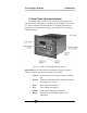
Figure 1-1: Model 3000TA-XL-EU Front Panel 3
Figure 1-2: Model 3000TA-XL Rear Panel 6
Figure 2-1: Micro-Fuel Cell 8
Figure 2-2: Cross Section of a Micro-fuel Cell (not to scale) 9
Figure 2-3: Characteristic Input/Output Curve for a Micro-Fuel
Cell 11
Figure 2-4: Piping Layout 13
Figure 2-5A: Flow Diagram—Sample Under Pressure-Standard 14
Figure 2-5B: Flow Diagram—Low Pressure-Model 3000TA-XL-VS14
Figure 2-5C: Flow Diagram—Sample Under Pressure-Model
3000TA-XL-CV 14
Figure 2-6: Power supply and PCB Location 15
Figure 2-7: Block Diagram of the Model 3000TA-XL-EU
Electronics 16
Figure 3-1: Front Panel of the Model 3000TA-XL-EU 20
Figure 3-2: Required Front Door Clearance 20
Figure 3-3: Rear Panel of the Model 3000TA-XL-EU 21
Figure 3-4: Equipment Interface Connector Pin Arrangement 23
Figure 3-5: Remote Probe Connections 29
Figure 3-6: FET Series Resistance 29
Figure 3-7: Installing the B-2CXL MFC (other cells similar) 32
Figure 3-8: Installing the Insta-Trace Micro-fuel Cell 34
Figure 4-1: Hierarchy of Available Functions 39
Figure 5-1: Analyzer Status Window—Running 64
Figure 5-2: Span Calibration Window 66
Figure 5-3: Zero Calibration Window 67
Figure 5-4: Set Alarms Window 68