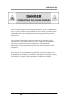
Trace Oxygen Analyzer OPERATING INSTRUCTIONS FOR MODEL 3000TA-XL-EU Trace Oxygen Analyzer P/N M69603 12/02/13 DANGER Toxic gases and or flammable liquids may be present in this monitoring system. Personal protective equipment may be required when servicing this instrument. Hazardous voltages exist on certain components internally which may persist for a time even after the power is turned off and disconnected. Only authorized personnel should conduct maintenance and/or servicing.
3000TA-XL-EU Copyright © 2013 Teledyne Analytical Instruments All Rights Reserved. No part of this manual may be reproduced, transmitted, transcribed, stored in a retrieval system, or translated into any other language or computer language in whole or in part, in any form or by any means, whether it be electronic, mechanical, magnetic, optical, manual, or otherwise, without the prior written consent of Teledyne Analytical Instruments, 16830 Chestnut Street, City of Industry, CA 91748.
Trace Oxygen Analyzer Teledyne Analytical Instruments iii
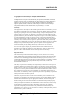
3000TA-XL-EU Specific Model Information The instrument for which this manual was supplied may incorporate one or more options not supplied in the standard instrument. Commonly available options are listed below, with check boxes. Any that are incorporated in the instrument for which this manual is supplied are indicated by a check mark in the box.
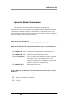
Trace Oxygen Analyzer Important Notice Model 3000TA-XL-EU complies with all of the requirements of the Commonwealth of Europe (CE) for Radio Frequency Interference, Electromagnetic Interference (RFI/EMI), and Low Voltage Directive (LVD). The following International Symbols are used throughout the Instruction Manual. These symbols are visual indicators of important and immediate warnings and when you must exercise CAUTION while operating the instrument. See also the Safety Information on the next page.
3000TA-XL-EU Safety Messages Your safety and the safety of others is very important. We have provided many important safety messages in this manual. Please read these messages carefully. A safety message alerts you to potential hazards that could hurt you or others. Each safety message is associated with a safety alert symbol. These symbols are found in the manual and inside the instrument.
Trace Oxygen Analyzer CAUTION: THE ANALYZER SHOULD ONLY BE USED FOR THE PURPOSE AND IN THE MANNER DESCRIBED IN THIS MANUAL. IF YOU USE THE ANALYZER IN A MANNER OTHER THAN THAT FOR WHICH IT WAS INTENDED, UNPREDICTABLE BEHAVIOR COULD RESULT POSSIBLY ACCOMPANIED WITH HAZARDOUS CONSEQUENCES. This manual provides information designed to guide you through the installation, calibration and operation of your new analyzer. Please read this manual and keep it available.
3000TA-XL-EU This is a general purpose instrument designed for use in a nonhazardous area. It is the customer's responsibility to ensure safety especially when combustible gases are being analyzed since the potential of gas leaks always exist. The customer should ensure that the principles of operation of this equipment are well understood by the user.
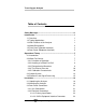
Trace Oxygen Analyzer Table of Contents Safety Messages .......................................................................... vi Introduction ................................................................................... 1 1.1 Overview 1 1.2 Typical Applications 1 1.3 Main Features of the Analyzer 1 1.4 Model Designations 2 1.5 Front Panel (Operator Interface) 3 1.6 Rear Panel (Equipment Interface) 5 Operational Theory ....................................................................... 7 2.
3000TA-XL-EU 3.3.2.2.1 Analog Outputs 3.3.2.2.2 Alarm Relays 3.3.2.2.3 Digital Remote Cal Inputs 3.3.2.2.4 Cal Contact 3.3.2.2.5 Remote Calibration Protocol 3.3.2.2.6 Range ID Relays 3.3.2.2.7 Network I/O 3.3.2.2.8 Remote Valve Connections 3.3.2.3 RS-232 Port 3.4 Installing the Micro-fuel Cell 3.4.1 B-2CXL Micro-fuel Cell 3.4.2 Insta-Trace Micro-fuel Cell 3.5 Testing the System 23 24 26 26 27 27 28 28 30 31 31 32 34 Operation ...............................................................................
Trace Oxygen Analyzer 4.4.2.1 Auto Mode Spanning 4.4.2.2 Manual Mode Spanning 4.4.3 Span Failure 4.5 Switching of Sample Streams 4.5.1 Special Notes on Hydrogen Gas Stream 4.6 The Alarms Function 4.7 The Range Function 4.7.1 Setting the Analog Output Ranges 4.7.2 Fixed Range Analysis 4.8 The Analyze Function 4.9 Signal Output 4.10 The IP Address Function 4.11 Cold Boot to Return to Default Settings 51 52 53 54 55 55 57 58 59 59 60 61 62 Web Implementation .................................................
3000TA-XL-EU 6.5 Major Internal Components 6.6 Cleaning 6.7 Troubleshooting 80 81 81 Appendix ...................................................................................... 83 A-1 Specifications 83 A-2 Recommended 2-Year Spare Parts List 85 A-3 Drawing List 86 A-4 19-inch Relay Rack Panel Mount 86 A.
Trace Oxygen Analyzer List of Figures Figure 1-1: Model 3000TA-XL-EU Front Panel 3 Figure 1-2: Model 3000TA-XL Rear Panel 6 Figure 2-1: Micro-Fuel Cell 8 Figure 2-2: Cross Section of a Micro-fuel Cell (not to scale) 9 Figure 2-3: Characteristic Input/Output Curve for a Micro-Fuel Cell 11 Figure 2-4: Piping Layout 13 Figure 2-5A: Flow Diagram—Sample Under Pressure-Standard 14 Figure 2-5B: Flow Diagram—Low Pressure-Model 3000TA-XL-VS14 Figure 2-5C: Flow Diagram—Sample Under Pressure-Model 3000TA-XL-CV 14 Fi
3000TA-XL-EU Figure 5-5: Set Range Window Figure 5-6: System Window Figure 5-7: Self-Test Window Figure 6-1: Removing the Micro-Fuel Figure 6-2: Installing the Insta-Trace Cell Figure 6-3: Removing Fuse Block from Housing Figure 6-4: Installing Fuses Figure 6-5: Rear Panel Removal Figure A-1: Single and Dual 19" Rack Mounts Teledyne Analytical Instruments 69 70 71 76 77 78 79 80 86 xiv
Trace Oxygen Analyzer List of Tables Table 3-1: Analog Output Connections Table 3-2: Alarm Relay Contact Pins Table 3-3: Remote Calibration Connections Table 3-4: Range ID Relay Connections Table 3-5: Commands via RS-232 Input Table 3-6: Required RS-232 Options Table 4-1: Output Signals Table 4-2: Range ID Output Voltage Table 6-1: Self Test Failure Codes Teledyne Analytical Instruments 24 25 26 28 30 30 60 61 79 xv
Trace Oxygen Analyzer Introduction Introduction 1.1 Overview The Teledyne Analytical Instruments Model 3000TA-XL-EU Trace Oxygen Analyzer is a versatile microprocessor-based instrument for detecting oxygen at the parts-per-million (ppm) level in a variety of gases. This manual covers the Model 3000TA-XL-EU General Purpose flush-panel and/or rack-mount units only. These units are for indoor use in a nonhazardous environment. 1.
Introduction 3000TA-XL-EU Advanced Micro-Fuel Cell, designed for trace analysis, has a 0-1 ppm low range with less than a 0.2 ppm offset and six months warranty and an expected lifetime of one year. Versatile analysis over a wide range of applications. Microprocessor based electronics: 8-bit CMOS microprocessor with 32 kB RAM and 128 kB ROM. Three user definable output ranges (from 0-1 ppm through 0250,000 ppm) allow best match to users process and equipment.
Trace Oxygen Analyzer Introduction 1.5 Front Panel (Operator Interface) The standard 3000TA-XL-EU is housed in a rugged metal case with all controls and displays accessible from the front panel. See Figure 1-1. The front panel has thirteen buttons for operating the analyzer, a digital meter, an alphanumeric display, and a window for viewing the sample flowmeter.
Introduction 3000TA-XL-EU Data Entry Keys: Six touch-sensitive membrane switches are used to input data to the instrument via the alphanumeric VFD display: Left & Right Arrows Select between functions currently displayed on the VFD screen. Up & Down Arrows Increment or decrement values of functions currently displayed. Enter Advances VFD display to the next screen in a series or returns to the Analyze screen if none remain.
Trace Oxygen Analyzer Introduction requires unfastening rear panel screws and sliding the unit out of the case. 1.6 Rear Panel (Equipment Interface) The rear panel, shown in Figure 1-2, contains the gas and electrical connectors for external inlets and outlets. Some of those depicted are optional and may not appear on your instrument. The connectors are described briefly here and in detail in Chapter 3 Installation. Power Connection Universal AC power source.
Introduction 3000TA-XL-EU Note: If you require highly accurate Auto-Cal timing, use external Auto-Cal control where possible. The internal clock in the Model 3000TA-XL is accurate to 2-3 %. Accordingly, internally scheduled calibrations can vary 2-3 % per day.
Trace Oxygen Analyzer Operational Theory Operational Theory 2.1 Introduction The analyzer is composed of three subsystems: 1. Micro-fuel Cell Sensor 2. Sample System 3. Electronic Signal Processing, Display and Control The sample system is designed to accept the sample gas and transport it through the analyzer without contaminating or altering the sample prior to analysis.
Operational Theory 3000TA-XL-EU between a battery and a true fuel cell. (All of the reactants are stored externally in a true fuel cell.) 2.2.2 Anatomy of a Micro-Fuel Cell The Micro-Fuel Cell is a cylinder only 1¼ inches in diameter and 1¼ inches thick. It is made of an extremely inert plastic, which can be placed confidently in practically any environment or sample stream. It is effectively sealed, although one end is permeable to oxygen in the sample gas.
Trace Oxygen Analyzer Operational Theory Figure 2-2: Cross Section of a Micro-fuel Cell (not to scale) The anode structure is below the cathode. It is made of lead and has a proprietary design which is meant to maximize the amount of metal available for chemical reaction. At the rear of the cell, just below the anode structure, is a flexible membrane designed to accommodate the internal volume changes that occur throughout the life of the cell.
Operational Theory 3000TA-XL-EU When the oxygen is reduced at the cathode, lead is simultaneously oxidized at the anode by the following HALF REACTION: – +2 – Pb + 2OH → Pb + H2O + 2e (anode) (Two electrons are transferred for each atom of lead that is oxidized. Therefore it takes two of the above anode reactions to balance one cathode reaction and transfer four electrons.) The electrons released at the surface of the anode flow to the cathode surface when an external electrical path is provided.
Trace Oxygen Analyzer Operational Theory directly proportional to the concentration of oxygen in the gaseous mixture. In other words it has a linear characteristic curve, as shown in Figure 2-3. Measuring circuits do not have to compensate for nonlinearities. In addition, since there is zero output in the absence of oxygen, the characteristic curve has close to an absolute zero (less than ± 0.2 ppm oxygen). This means there is usually no need to zero calibrate the instrument.
Operational Theory 3000TA-XL-EU If, however, a low range accuracy better than 100 ppb is required, then a zero calibration is recommended. See Section 4.4.1. 2.3 Sample System The sample system delivers gases to the Micro-fuel Cell sensor from the analyzer rear panel inlet. Depending on the mode of operation either sample or calibration gas is delivered.
Trace Oxygen Analyzer Operational Theory Figure 2-4: Piping Layout Teledyne Analytical Instruments 13
Operational Theory 3000TA-XL-EU Figure 2-5A: Flow Diagram—Sample Under Pressure-Standard Figure 2-5B: Flow Diagram—Low Pressure-Model 3000TA-XL-VS Figure 2-5C: Flow Diagram—Sample Under Pressure-Model 3000TAXL-CV Teledyne Analytical Instruments 14
Trace Oxygen Analyzer Operational Theory 2.4 Electronics and Signal Processing The Model 3000TA-XL-EU Trace Oxygen Analyzer uses an 8031 microcontroller with 32 kB of RAM and 128 kB of ROM to control all signal processing, input/output, and display functions for the analyzer. System power is supplied from a universal power supply module designed to be compatible with any international power source. Figure 2-6 shows the location of the power supply and the main electronic PC boards.
Operational Theory 3000TA-XL-EU Figure 2-7: Block Diagram of the Model 3000TA-XL-EU Electronics Teledyne Analytical Instruments 16
Trace Oxygen Analyzer Operational Theory In the presence of oxygen the cell generates a current. A current to voltage amplifier converts this current to a voltage, which is amplified in the second stage amplifier. The second stage amplifier also supplies temperature compensation for the oxygen sensor output. This amplifier circuit incorporates a thermistor, which is physically located in the cell block.
Operational Theory 3000TA-XL-EU Teledyne Analytical Instruments 18
Trace Oxygen Analyzer Installation Installation Installation of the Model 3000TA-XL-EU Analyzer includes: 1. Unpacking 2. Mounting 3. Gas connections 4. Electrical connections 5. Installing the Micro-Fuel Cell 6. Testing the system. 3.1 Unpacking the Analyzer The analyzer is shipped with all the materials you need to install and prepare the system for operation. Carefully unpack the analyzer and inspect it for damage. Immediately report any damage to the shipping agent. 3.
Installation 3000TA-XL-EU Figure 3-1: Front Panel of the Model 3000TA-XL-EU All operator controls, except the flow control needle valve, are mounted on the control panel, which is hinged on the left edge and doubles as the door that provides access to the sensor and cell block inside the instrument. The door latch is spring loaded and will swing open when the button in the center of the latch (upper right corner) is pressed all the way in with a narrow gauge tool (less than 0.18 inch wide).
Trace Oxygen Analyzer Installation 3.3 Rear Panel Connections Figure 3-3 shows the Model 3000TA-XL-EU rear panel. There are ports for gas inlet and outlet, power, communication, and both digital and analog concentration output via the 50-pin Equipment Interface Connector. Figure 3-3: Rear Panel of the Model 3000TA-XL-EU 3.3.1 Gas Connections Note: Do not remove plastic caps on VCR fittings, unless you are ready to make connections.
Installation 3000TA-XL-EU SAMPLE IN: In the standard model, gas connections are made at the SAMPLE IN and EXHAUST OUT connections. Calibration gases must be tee'd into the sample inlet with appropriate valves. A VCR fitting is provided for the inlet connection. The inlet gas pressure should be reasonably regulated. Pressures between 2 and 50 psig are acceptable as long as the pressure, once established, will keep the front panel flowmeter reading in an acceptable range (0.5 to 2.0 SLPM).
Trace Oxygen Analyzer Installation 3.3.2.1 PRIMARY INPUT POWER The power cord receptacle and fuse block are located in the same assembly. Insert the power cord into the power cord receptacle. CAUTION: POWER IS APPLIED TO THE INSTRUMENT'S CIRCUITRY AS LONG AS THE INSTRUMENT IS CONNECTED TO THE POWER SOURCE. THE RED SWITCH ON THE FRONT PANEL IS FOR SWITCHING POWER ON OR OFF TO THE DISPLAYS AND OUTPUTS ONLY. The universal power supply requires an 85–250 VAC, 47-63 Hz power source.
Installation 3000TA-XL-EU 0–1 V DC % of Range: Voltage rises linearly with increasing oxygen, from 0 V at 0 ppm to 1 V at full scale ppm. (Full scale = 100% of programmable range.) 0–1 VDC Range ID: 0.25 V = Low Range 0.5 V = Medium Range 0.75 V = High Range 1 V = Air Cal Range. 4–20 mA DC % Range: Current increases linearly with increasing oxygen, from 4 mA at 0 ppm to 20 mA at full scale ppm.
Trace Oxygen Analyzer Installation Threshold Alarm 1: Can be configured as high (actuates when concentration is above threshold), or low (actuates when concentration is below threshold). Can be configured as failsafe or non-failsafe. Can be configured as latching or non-latching. Can be configured out (defeated). Threshold Alarm 2: Can be configured as high (actuates when concentration is above threshold), or low (actuates when concentration is below threshold).
Installation 3000TA-XL-EU 43 Threshold Alarm 2, normally open contact 36 System Alarm, normally closed contact 20 System Alarm, moving contact 37 System Alarm, normally open contact 3.3.2.2.3 Digital Remote Cal Inputs These inputs accept 0 V (off) or 24 VDC (on) inputs for remote control of calibration. (See Remote Calibration Protocol below.) See Table 3-3 for pin connections. Zero: Floating input. 5 to 24 V input across the + and – pins puts the analyzer into the Zero mode.
Trace Oxygen Analyzer Installation 40 Cal Contact 41 Cal Contact 3.3.2.2.5 Remote Calibration Protocol To properly time the Digital Remote Cal Inputs to the Model 3000TA-XL-EU Analyzer, the customer's controller must monitor the Cal Relay Contact. When the contact is OPEN, the analyzer is analyzing, the Remote Cal Inputs are being polled, and a zero or span command can be sent. When the contact is CLOSED, the analyzer is already calibrating.
Installation 3000TA-XL-EU 1 ID, Medium range is assigned to Range 2 ID, and High range is assigned to Range 3 ID. The fourth range is reserved for the Air Cal Range (25%). Table 3-4 lists the pin connections. Table 3-4: Range ID Relay Connections Pin Function 21 Range 1 ID Contact 38 Range 1 ID Contact 22 Range 2 ID Contact 39 Range 2 ID Contact 19 Range 3 ID Contact 18 Range 3 ID Contact 34 Range 4 ID Contact (Air Cal) 35 Range 4 ID Contact (Air Cal) 3.3.2.2.
Trace Oxygen Analyzer Installation Figure 3-5: Remote Probe Connections The voltage from these outputs is nominally 0 V for the OFF and 15 VDC for the ON conditions. The maximum combined current that can be pulled from these output lines is 100 mA. (If two lines are ON at the same time, each must be limited to 50 mA, etc.) If more current and/or a different voltage is required, use a relay, power amplifier, or other matching circuitry to provide the actual driving current.
Installation 3000TA-XL-EU 3.3.2.3 RS-232 PORT The digital signal output is a standard, full duplex RS-232 serial communications port used to connect the analyzer to a computer, terminal, or other digital device. It requires a standard 9-pin D connector. The output data is status information, in digital form, updated every two seconds.
Trace Oxygen Analyzer Installation Byte 8 bits Parity none Stop Bits Message Interval 1 2 seconds. When CRC opens again, zero and span are done, and the sample is being analyzed. 3.4 Installing the Micro-fuel Cell The Model 3000TA-XL-EU can be equipped with either the standard B-2CXL Micro-fuel Cell or as an option, Teledyne’s InstaTrace cell. An existing instrument can also be retrofitted to use the InstaTrace cell using Teledyne retrofit kit P/N C-71792-A.
Installation 3000TA-XL-EU MINIMUM AMOUNT OF TIME, INCLUDING DURING INSTALLATION. Use care to minimize the exposure of the sensor to air. A 3-5 minute exposure to air may require 24 hours or longer cell recovery period before the cell recovers to less than 0.5 ppm on an oxygen free sample gas. On the other hand, if the air exposure is limited to less than 10 seconds, the recovery time will be reduced to two hours, or less.
Trace Oxygen Analyzer Installation The following procedure can be used to install the Insta-Trace Micro-fuel Cell: Note: Even though the Insta-Trace Micro-fuel Cell has a short recovery time after ambient air exposure, minimizing this exposure still reduces the recovery time necessary. CAUTION: DO NOT TOUCH THE SENSING SURFACE OF THE CELL. IT IS COVERED WITH A DELICATE TEFLON MEMBRANE THAT CAN LEAK WHEN PUNCTURED. Before installing a new cell. check the O-ring in the base of the cell holder.
Installation 3000TA-XL-EU 9. Purge the system using sample or zero gas. 10. Power the system back up. The Insta-Trace sensor will typically reach a stable low value within 30 minutes or less after installation. Figure 3-8: Installing the Insta-Trace Micro-fuel Cell 3.5 Testing the System Before plugging the instrument into the power source: Check the integrity and accuracy of the gas connections. Make sure there are no leaks. Check the integrity and accuracy of the electrical connections.
Trace Oxygen Analyzer Installation Check that inlet sample pressure is within the accepted range (see Section 3.3.1). Power up the system, and test it by repeating the SelfDiagnostic Test as described in Chapter 4, Section 4.3.5.
Installation 3000TA-XL-EU Teledyne Analytical Instruments 36
Trace Oxygen Analyzer Operation Operation 4.1 Introduction Once the analyzer has been installed, it can be configured for your application. To do this you will: Set system parameters. Establish a security password, if desired, requiring Operator to log in. Establish and start an automatic calibration cycle, if desired. Calibrate the instrument. Define the three user selectable analysis ranges, then choose autoranging or select a fixed range of analysis, as required.
Operation 3000TA-XL-EU 4.2 Using the Data Entry and Function Buttons Data Entry Buttons: The ◄► arrow buttons select options from the menu currently being displayed on the VFD screen. The selected option blinks. When the selected option includes a modifiable item, the ▲▼ arrow buttons can be used to increment or decrement that modifiable item. The Enter button is used to accept any new entries on the VFD screen.
Trace Oxygen Analyzer Operation Figure 4-1: Hierarchy of Available Functions Any function can be selected at any time by pressing the appropriate button (unless password restrictions apply). The order as presented in this manual is appropriate for an initial setup. Each of these functions is described in greater detail in the following procedures. The VFD screen text that accompanies each operation is reproduced, at the appropriate point in the procedure, in a Arial Narrow Bold type style.
Operation 3000TA-XL-EU 4.3 The System Function The sub functions of the System function are described below. Specific procedures for their use follow the descriptions: Auto-Cal: Used to define an automatic calibration sequence and/or start an Auto-Cal. PSWD: Security can be established by choosing a 5 digit password (PSWD) from the standard ASCII character set. (See Installing or Changing the Password, below, for a table of ASCII characters available.
Trace Oxygen Analyzer Operation 4.3.1 Tracking the Oxygen Readings During Calibration and Alarm Delay The user has the option of setting the preferences as to whether the analog outputs track the display readings during calibration or not. To set the preference, press the System key once and the first System menu will appear in the VFD display: TRAK/HLD Auto-Cal PSWD Logout More TRAK/HLD should be blinking.
Operation 3000TA-XL-EU The factory default is three minutes, but the delay time is programmable. To adjust to delay time use the Left or Right arrow keys. When the time displayed on the second line blinks, it can be adjusted by Pressing the Up or Down keys to increase or decrease its value. The minimum delay is 1 minute, the maximum is 30. This preference is stored in non-volatile memory so that it is recovered if power is removed from the instrument. 4.3.
Trace Oxygen Analyzer Operation Press ◄► arrows to blink Span (or Zero), then press Enter again. (You won’t be able to set OFF to ON if a zero interval is entered.) A Span Every ... (or Zero Every ...) screen appears. Span Every 0 d Start 0 h from now Use ▲▼ arrows to set an interval value, then use ◄► arrows to move to the start-time value. Use▲▼ arrows to set a start-time value. To turn ON the Span and/or Zero cycles (to activate Auto-Cal): Press System again, choose Auto—Cal, and press Enter again.
Operation 3000TA-XL-EU Use the ◄► arrow keys to scroll the blinking over to PSWD, and press Enter to select the password function. Either the default TETAI password or AAAAA place holders for an existing password will appear on screen depending on whether or not a password has been previously installed. TETAI Enter PWD —or— AAAAA Enter PWD The screen prompts you to enter the current password. If you are not using password protection, press Enter to accept TETAI as the default password.
Trace Oxygen Analyzer Operation Press Enter to change the password (either the default TETAI or the previously assigned password), or press Escape to keep the existing password and move on. If you chose Enter to change the password, the password assignment screen appears. TETAI To Proceed —or— AAAAA To Proceed Enter the password using the ◄► arrow keys to move back and forth between the existing password letters, and the ▲▼ arrow keys to change the letters to the new password.
Operation 3000TA-XL-EU Wait a moment for the entry screen. You will be given clearance to proceed. AAAAA TO Proceed Use the arrow keys to retype your password and press Enter when finished. Your password will be stored in the microprocessor and the system will immediately switch to the Analyze screen, and you now have access to all instrument functions. If all alarms are defeated, the Analyze screen appears as: 0.
Trace Oxygen Analyzer Operation 4.3.5 System Self-Diagnostic Test The Model 3000TA-XL-EU has a built-in self-diagnostic testing routine. Pre-programmed signals are sent through the power supply, output board and sensor circuit. The return signal is analyzed, and at the end of the test the status of each function is displayed on the screen, either as OK or as a number between 1 and 3. (See System Self Diagnostic Test in Chapter 6 for number code).
Operation 3000TA-XL-EU 4.3.6 Version Screen Move the ◄► arrow key to More and press Enter. With Version blinking, press Enter. The screen displays the manufacturer, model, and software version information. 4.4 Calibration of the Analyzer The analyzer must be calibrated prior to its use. The following sections describe how to calibrate the analyzer. If equipped with remote calibration valves, the analyzer can be calibrated from a remote terminal using the RS-232 port. See Section 3.3.2.3.
Trace Oxygen Analyzer Operation 4.4.1 Zero Cal The B-2CXL cell has a zero offset of less than 0.2 ppm oxygen. Normally, the offset slowly decreases during the first 7 to 10 days of operation, and is expected to reach a steady value after this time. Generally, the value of the zero offset is part of the oxygen reading of the sample gas as shown by the analyzer readout. As an example, a reading of 0.5 ppm oxygen may include 0.4 ppm oxygen in the sample gas and a 0.1 ppm zero offset.
Operation 3000TA-XL-EU #### PPM Zero Slope=#### ppm/s The beginning zero level is shown in the upper left corner of the display. As the zero reading settles, the screen displays and updates information on Slope (unless the Slope starts within the acceptable zero range and does not need to settle further). Then, and whenever Slope is less than 0.08 for at least 3 minutes, instead of Slope you will see a countdown: 5 Left, 4 Left, and so fourth.
Trace Oxygen Analyzer Operation Generally, you have a good zero when Slope is less than 0.05 ppm/s for about 30 seconds. When Slope is close enough to zero, press Enter. In a few seconds, the screen will update. Once zero settling is completed, the information is stored in the microprocessor, and the instrument automatically returns to the Analyze mode. 4.4.1.
Operation 3000TA-XL-EU Span: Settling: AUTO For Next Press Enter to move to the next screen. Calib. Holding time Cal hold: 5 min This menu allows the operator to set the time the analyzer should be held in the AUTO span mode, after the readings of the analyzer settle. Five minutes is the default, but it could be adjusted anywhere from 1 to 60 minutes by using the ▲▼ keys. Press Enter to move to the next screen. Span Val: 000008.
Trace Oxygen Analyzer Operation Calib. Holding time Cal hold: 5 min This menu allows the operator to set the time the analyzer should be held in the AUTO span mode. It does not have any effect in the MANual mode. Just press Enter key to continue. Span Val: 000008.00 Span Mod # Press ▲ () to permit modification (Mod #) of span value. Use the arrow keys to enter the oxygen concentration of the span gas you are using (209000.00 if you are using air).
Operation 3000TA-XL-EU VFD display “FCAL” will be shown. This message flag will help the operator troubleshoot in case calibration was initiated remotely. To reset the alarm and the flag message, the unit must be turned off by cycling the standby key . It will reset if the next span cycle is correct. A trace cell is unlikely to fail span. As explained before, when the sensor reaches the end of its useful life, the zero offset begins to rise until the analyzer finds the zero unsatisfactory.
Trace Oxygen Analyzer Operation 4.5.1 Special Notes on Hydrogen Gas Stream The standard oxygen cells, Model B-2CXL and Insta-Trace, though tested in nitrogen gas streams, are expected to perform well in hydrogen streams. However, for certain applications such as continuous monitoring of very low levels of oxygen in hydrogen, the user may request cells that have been specifically tested in hydrogen streams. Consult Teledyne for further details. 4.
Operation 3000TA-XL-EU 3. Are either or both of the alarms to be configured as failsafe? You can set either or both of the concentration alarms to operate in failsafe or non-failsafe mode. In failsafe mode, the alarm relay de-energizes in an alarm condition. For non-failsafe operation, the relay is energized in an alarm condition. 4.
Trace Oxygen Analyzer Operation Value of the alarm setpoint, AL–1 #### ppm (oxygen); this value can be set from 0.00 to 10,000.00 ppm Out-of-range direction, HI or LO Defeated? Dft–Y/N (Yes/No) Failsafe? Fs–Y/N (Yes/No) Latching? Ltch–Y/N (Yes/No). To define the setpoint, use the ◄► arrow keys to move the blinking over to AL–1 ####. Then use the ▲▼ arrow keys to change the number. Holding down the key speeds up the incrementing or decrementing. (Remember, the setpoint units are ppm O2.
Operation 3000TA-XL-EU below 85% of full scale of the next lower range, the instrument will switch to that range. A corresponding shift in the DC percent-of-range output, and in the range ID outputs, will be noticed. The autoranging feature can be overridden so that analog output stays on a fixed range regardless of the oxygen concentration detected. If the concentration exceeds the upper limit of the range, the DC output will saturate at 1 VDC (20 mA at the current output).
Trace Oxygen Analyzer Operation 4.7.2 Fixed Range Analysis The autoranging mode of the instrument can be overridden, forcing the analyzer DC outputs to stay in a single predetermined range. To switch from autoranging to fixed range analysis, enter the range function by pressing the Range button on the front panel. Use the ◄► arrow keys to move the blinking over AUTO.
Operation 3000TA-XL-EU 4.9 Signal Output The standard Model 3000TA-XL-EU Trace Oxygen Analyzer is equipped with two 0–1 VDC analog output terminals accessible on the back panel (one concentration and one range ID), and two isolated 4–20 mA DC current outputs (one concentration and one range ID). See Rear Panel in Chapter 3, Installation, for illustration. The signal output for concentration is linear over the currently selected analysis range.
Trace Oxygen Analyzer Operation current when using the current outputs) to represent a particular range. The following table gives the range ID output for each analysis range: Table 4-2: Range ID Output Voltage Range Voltage (V) Current (mA) LO 0.25 8 MED 0.50 12 HI 0.75 16 CAL (0-25%) 1.00 20 IMPORTANT: In the event of loss of flow through the analyzer, if the vent is vented to a location of high oxygen content, oxygen will back diffuse through the vent line and enter the cell.
Operation 3000TA-XL-EU Ethernet web server coprocessor. To set the IP address, enter the system menu: Ver SysTest Sample AL-Hld Temp-Set IP Select IP and press Enter. The last IP address setting will be shown: IP NUMBER 172.016.032.254 Adjust each field separated by a point using the Up/Down keys and hop to the next field by using the Right/Left arrow keys. Once the address is set, press the Enter key. The 3000 microcontroller will send the new address to the Ethernet Web Enabled co-processor.
Trace Oxygen Analyzer Web Implementation Web Implementation 5.1 The Embedded Browser The 3000TA-XL-I series instruments come with an Ethernet Web Enabled co-processor. This means that all you need is an Ethernet connection to access the analyzer remotely through an internet browser such as Microsoft® Explorer. The following three steps will web enable your instrument: 1. Follow the instructions in Chapter 4 Section 4.
Web Implementation 3000TA-XL-EU Figure 5-1: Analyzer Status Window—Running This screen shows the relevant status of the analyzer, such as oxygen reading, current range, alarm status, etc. On the top of the web page there are six functions that can be accessed by clicking on the six buttons.
Trace Oxygen Analyzer System Self Test Web Implementation These functions are described in the following sections. Below the six buttons is a small message window. In normal mode it would read ‘Running’ and actions can be performed, such as pushing buttons and modifying values. When ‘Getting Data’ is displayed, the co-processor is busy performing a request. While ‘Getting Data’ is displayed, the operator should not click buttons or interact with the browser.
Web Implementation 3000TA-XL-EU Figure 5-2: Span Calibration Window Teledyne Analytical Instruments 66
Trace Oxygen Analyzer Web Implementation 5.2.2 Remote Zero To perform a remote zero, click the Zero button at the top of the HTML page. A zero calibration window will open. In this window the operator can set zero operation to be automatic or manual. Once set, click the Start button. If an auto calibration was chosen, the operator must wait for the analyzer to finish the calibration. In the main data window, the field 'mode' will switch from 'analyzing' to 'getting zero'.
Web Implementation 3000TA-XL-EU 5.3 Set the Alarms Remotely To set the concentration alarms, Alarm 1 and Alarm 2, click on the Alarm button. The setup menu for both alarms will appear on the left side of the web page. After a few seconds, the page will be updated with current settings on the alarms. To find out what each function does, refer to the alarm section in Chapter 4. Only one alarm can be set each time.
Trace Oxygen Analyzer Web Implementation 5.4 Set the Ranges Remotely With the 3000TA-XL-EU-I, it is possible to change range settings remotely. Click on the Range button and the range menu will appear on the left side of the web page. After a few seconds, the data area will show the current settings of the instrument. The operator can perform changes such as fixing the analyzer in a single range or auto ranging.
Web Implementation 3000TA-XL-EU 5.5 System Menu By clicking the System button some settings found in the system menu from the front of the control panel can be set, such as: Zero Offset, Alarm Delay, and Auto Calibration. Description of these settings can be found in Chapter 4.
Trace Oxygen Analyzer Web Implementation 5.6 The Self-Test function Clicking on the Self Test button will initiate an analog selfdiagnostic in the instrument. Watch the message window for acknowledgement that the instrument entered the self-diagnostic mode. In the main data window, the field 'mode' will switch from 'analyzing' to 'self-test'. The self-test should not take more than one minute for a 3000TA-XL-EU-I. During this time, do not click on any buttons.
Web Implementation 3000TA-XL-EU Teledyne Analytical Instruments 72
Trace Oxygen Analyzer Maintenance Maintenance 6.1 Routine Maintenance Aside from normal cleaning and checking for leaks at the gas connections, routine maintenance is limited to replacing Micro-Fuel cells and fuses, and recalibration. For recalibration, see Section 4.4 Calibration. WARNING: SEE WARNINGS ON THE TITLE PAGE OF THIS MANUAL. 6.
Maintenance 3000TA-XL-EU The spare cell should be carefully stored in an area that is not subject to large variations in ambient temperature (75°F nominal) or to rough handling. WARNING: The sensors used in the model 3000TA-XL-EU Trace Oxygen Analyzer uses electrolytes which contain toxic substances, mainly lead and potassium hydroxide, that can be harmful if touched, swallowed, or inhaled. Avoid contact with any fluid or powder in or around the unit.
Trace Oxygen Analyzer Maintenance 6.2.3 Removing the Micro-Fuel Cell The Micro-Fuel cell is located inside the stainless steel cell block behind the front panel. Refer to Figure 6-1 for the B-2CXL cell and Figure 6-2 for the Insta-Trace cell. To remove an existing cell: 1. Remove power to the instrument by unplugging the power cord at the power source. 2. Open the front panel door by pressing the release button on the top right corner of the door all the way in with a narrow gauge tool. 3.
Maintenance 3000TA-XL-EU Figure 6-1: Removing the Micro-Fuel Teledyne Analytical Instruments 76
Trace Oxygen Analyzer Maintenance Figure 6-2: Installing the Insta-Trace Cell 6.2.5 Cell Warranty The Class B-2CXL and the Insta-Trace Micro-fuel Cells are used in the Model 3000TA-XL-EU. These cells are warranted for 6 months from the date of shipment. Note any Addenda attached to the front of this manual for special information applying to your instrument. With regard to spare cells, warranty period begins on the date of shipment. The customer should purchase only one spare cell (per Section 6.2.1).
Maintenance 3000TA-XL-EU Consult TAI for the appropriate cell for measuring trace oxygen in the presence of CO2. If a cell was working satisfactorily, but ceases to function before the warranty period expires, the customer will receive credit toward the purchase of a new cell. If you have a warranty claim, you must return the cell in question to the factory for evaluation. If it is determined that failure is due to faulty workmanship or material, the cell will be replaced at no cost to you.
Trace Oxygen Analyzer Maintenance 3. Replace fuse as shown in Figure 6-4. 4. Reassemble Housing as shown in Figure 6-3. American Fuses European Fuses Figure 6-4: Installing Fuses 6.4 System Self Diagnostic Test 1. Press the System button to enter the system mode. 2. Use the ◄► arrow keys to move to More, and press Enter. 3. Use the ◄► arrow keys to move to Self-Test, and press Enter.
Maintenance 3000TA-XL-EU Preamp 0 1 2 3 OK Zero too high Amplifier output doesn't match test input Both Failed 6.5 Major Internal Components The Micro-fuel Cell is accessed by unlatching and swinging open the front panel, as described earlier. Other internal components are accessed by removing the rear panel and sliding out the entire chassis. See Figure 6-5, below. The gas piping is illustrated in Figures 2-4 and 2-5 and the major electronic components locations are shown in Figure 2-6, in Chapter 2.
Trace Oxygen Analyzer Maintenance The 3000TA-XL contains the following major components: Analysis Section Micro Fuel Cell (B-2CXL) Stainless steel cell block Sample system Power Supply Microprocessor Displays 5 digit LED meter 2 line, 20 character, alphanumeric, VFD display RS-232 Communications Port See the drawings in the Drawings section in back of this manual for details. 6.
Maintenance 3000TA-XL-EU Solution: Turn the analyzer off, then turn back on again. Press the System key when prompted by the analyzer "Press System for Default Values". This will return the analyzer to its default settings in calibration and zero values. If erratic behavior continues clean sensor contacts or replace the sensor. Possible Cause: Atmospheric oxygen may be diffusing in through the vent and affecting the oxygen level which the sensor sees.
Trace Oxygen Analyzer Appendix Appendix A-1 Specifications Packaging: General Purpose • Flush panel mount (Standard) • Relay rack mount. Contains either one or two instruments in one 19" relay rack mountable plate (Optional). Sensor: Teledyne B-2CXL trace analysis Microfuel Cell. Insta-Trace Micro-fuel Cell (option) Cell Block: 316 stainless steel. Sample System: All wetted parts of 316 stainless steel. 90 % Response Time: 65 seconds at 25°C (77°F) on 10 ppm range. 100 seconds on 1 ppm range.
Appendix 3000TA-XL-EU Power: Universal power supply 85-250 VAC, at 47-63 Hz. Operating Temperature: 5-35°C (41-95°F) Accuracy: ±2% of full scale at constant temperature on all ranges except 0-1 ppm. ±5% of full scale over operating temperature range, except 0-10 ppm and 0-1 ppm analysis range, once thermal equilibrium is reached. ±0.1 ppm on 0-1 ppm analysis range, once thermal equilibrium is reached. Analog outputs: 0-1 VDC percent-of-range, 0-1 VDC range ID.
Trace Oxygen Analyzer Appendix A-2 Recommended 2-Year Spare Parts List Qty.
Appendix 3000TA-XL-EU A-3 Drawing List D-69604 Outline Drawing A-4 19-inch Relay Rack Panel Mount Figure A-1: Single and Dual 19" Rack Mounts (dimensions in mm) Teledyne Analytical Instruments 86
Trace Oxygen Analyzer Appendix A.5 Application notes 3000XL SERIES ANALYZERS APPLICATION NOTES ON PRESSURES AND FLOW RECOMMENDATIONS The 3000 series analyzers require reasonably regulated sample pressures. While the 3000 analyzers are not sensitive to variations of incoming pressure provided they are properly vented to atmospheric pressure. The pressure must be maintained as to provide a useable flow rate trough the analyzer. Any line attached to sample vent should be 1/4 or larger in diameter.
Appendix 3000TA-XL-EU damage may occur. For cell pressures above atmospheric, caution must be exercised to avoid over pressuring the cell holder. FLOW CONTROL VALVE: All 3000XL series analyzers have a flow control device. This device is a needle valve, and serves two functions in the sample path: 1. It limits the flow rate of the sample through the analyzer. The needle valve is chosen to operate over a specific range of pressures and provide a useable flow rate over that range. 2.
Trace Oxygen Analyzer Appendix Material Safety Data Sheet Section I - Product Identification Product Name: Micro-fuel Cells Mini-Micro-fuel Cells Super Cell, all classes except T-5F Electrochemical Oxygen Sensors, all classes Manufacturer: Teledyne Electronic Technologies Analytical Instruments Address: 16380 Chestnut Street, City of Industry, CA 91749 Phone: (626) 961-9221 Technical Support: (626) 934-1673 Environment, Health and (626) 934-1592 Safety: Date Prepared: 11/23/98 Section II - Physical and C
Appendix 3000TA-XL-EU Section III -Physical Hazards Potential for fire and explosion: The electrolyte in the Micro-fuel Cells is not flammable. There are no fire or explosion hazards associated with Micro-fuel Cells. Potential for reactivity: The sensors are stable under normal conditions of use. Avoid contact between the sensor electrolyte and strong acids. Section IV - Health Hazard Data Primary route of entry: Ingestion, eye/skin contact Exposure limits: OSHA PEL: 0.05 mg./cu.m.
Trace Oxygen Analyzer Appendix Section V - Emergency and First Aid Procedures Eye Contact: Flush eyes with water for at least 15 minutes and get immediate medical attention. Skin Contact: Wash affected area with plenty of water and remove contaminated clothing. If burning persists, seek medical attention. Ingestion: Give plenty of cold water. Do not induce vomiting. Seek medical attention. Do not administer liquids to an unconscious person. Inhalation: Liquid inhalation is unlikely.
Appendix 3000TA-XL-EU Teledyne Analytical Instruments 92