OPERATING INSTRUCTIONS FOR MODEL 3000TA Trace Oxygen Analyzer P/N M66316 3/09/11 DANGER Toxic gases and or flammable liquids may be present in this monitoring system. Personal protective equipment may be required when servicing this instrument. Hazardous voltages exist on certain components internally which may persist for a time even after the power is turned off and disconnected. Only authorized personnel should conduct maintenance and/or servicing.
3000TA- EU Copyright © 2011 Teledyne Analytical Instruments All Rights Reserved. No part of this manual may be reproduced, transmitted, transcribed, stored in a retrieval system, or translated into any other language or computer language in whole or in part, in any form or by any means, whether it be electronic, mechanical, magnetic, optical, manual, or otherwise, without the prior written consent of Teledyne Analytical Instruments, 16830 Chestnut Street, City of Industry, CA 91749-1580.
Trace Oxygen Analyzer Specific Model Information The instrument for which this manual was supplied may incorporate one or more options not supplied in the standard instrument. Commonly available options are listed below, with check boxes. Any that are incorporated in the instrument for which this manual is supplied are indicated by a check mark in the box.
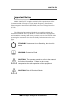
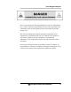
3000TA- EU Important Notice Model 3000TA-EU complies with all of the requirements of the Commonwealth of Europe (CE) for Radio Frequency Interference, Electromagnetic Interference (RFI/EMI), and Low Voltage Directive (LVD). The following International Symbols are used throughout the Instruction Manual. These symbols are visual indicators of important and immediate warnings and when you must exercise CAUTION while operating the instrument. See also the Safety Information on the next page.
Trace Oxygen Analyzer Safety Messages Your safety and the safety of others is very important. We have provided many important safety messages in this manual. Please read these messages carefully. A safety message alerts you to potential hazards that could hurt you or others. Each safety message is associated with a safety alert symbol. These symbols are found in the manual and inside the instrument.
3000TA- EU CAUTION: THE ANALYZER SHOULD ONLY BE USED FOR THE PURPOSE AND IN THE MANNER DESCRIBED IN THIS MANUAL. IF YOU USE THE ANALYZER IN A MANNER OTHER THAN THAT FOR WHICH IT WAS INTENDED, UNPREDICTABLE BEHAVIOR COULD RESULT POSSIBLY ACCOMPANIED WITH HAZARDOUS CONSEQUENCES. This manual provides information designed to guide you through the installation, calibration and operation of your new analyzer. Please read this manual and keep it available.
Trace Oxygen Analyzer This is a general purpose instrument designed for use in a nonhazardous area. It is the customer's responsibility to ensure safety especially when combustible gases are being analyzed since the potential of gas leaks always exist. The customer should ensure that the principles of operation of this equipment are well understood by the user.
3000TA- EU Table of Contents Safety Messages ........................................................................... v Introduction ................................................................................... 1 1.1 Overview 1 1.2 Typical Applications 1 1.3 Main Features of the Analyzer 1 1.4 Model Designations 2 1.5 Front Panel (Operator Interface) 3 1.6 Recognizing Difference Between LCD & VFD 4 1.7 Rear Panel (Equipment Interface) 5 Operational Theory .........................................
Trace Oxygen Analyzer 3.4 Installing the Micro-Fuel Cell 3.5 Testing the System 29 29 Operation ..................................................................................... 31 4.1 Introduction 31 4.2 Using the Data Entry and Function Buttons 31 4.3 The System Function 33 4.3.1 Tracking Oxygen Readings During Calibration and Alarm Delay 34 4.3.2 Setting up an Auto-Cal 36 4.3.3 Password Protection 37 4.3.3.1 Entering the Password 37 4.3.3.2 Installing or Changing the Password 38 4.3.4 Logout 40 4.
3000TA- EU 5.2.2 When to Replace a Cell 5.2.3 Removing the Micro-Fuel Cell 5.2.4 Installing a New Micro-Fuel Cell 5.2.5 Cell Warranty 5.3 Fuse Replacement 5.4 System Self Diagnostic Test 5.5 Major Internal Components 5.6 Cleaning 5.7 Troubleshooting 58 58 59 61 61 62 63 64 64 Appendix ......................................................................................
Trace Oxygen Analyzer List of Figures Figure 1-1: Model 3000TA Front Panel ........................................... 3 Figure 1-2: Model 3000 TA Rear Panel ........................................... 5 Figure 2-1: Micro-Fuel Cell .............................................................. 8 Figure 2-2. Cross Section of a Micro-Fuel Cell (not to scale) .......... 8 Figure 2-3. Characteristic Input/Output Curve for a Micro-Fuel Cell ......................................................................
3000TA- EU List of Tables Table 3-1: Analog Output Connections Pin Function .................... 23 Table 3-2: Alarm Relay Contact Pins ............................................ 24 Table 3-3: Remote Calibration Connections.................................. 25 Table 3-4: Range ID Relay Connections ....................................... 26 Table 3-5: Commands via RS-232 Input ....................................... 28 Table 5-1: Self Test Failure Codes ................................................
Trace Oxygen Analyzer Introduction Introduction 1.1 Overview The Teledyne Analytical Instruments Model 3000TA Trace Oxygen Analyzer is a versatile microprocessor-based instrument for detecting oxygen at the parts-per-million (ppm) level in a variety of gases. This manual covers the Model 3000TA General Purpose flushpanel and/or rack-mount units only. These units are for indoor use in a nonhazardous environment. 1.
Introduction 3000TA- EU Advanced Micro-Fuel Cell, designed for trace analysis, has a one year warranty and an expected lifetime of two years. Versatile analysis over a wide range of applications. Microprocessor based electronics: 8-bit CMOS microprocessor with 32 kB RAM and 128 kB ROM. Three user definable output ranges (from 0-10 ppm through 0- 250,000 ppm) allow best match to users process and equipment. Air-calibration range for convenient spanning at 20.9 %.
Trace Oxygen Analyzer Introduction 1.5 Front Panel (Operator Interface) The standard 3000TA is housed in a rugged metal case with all controls and displays accessible from the front panel. See Figure 1-1. The front panel has thirteen buttons for operating the analyzer, a digital meter, an alphanumeric display, and a window for viewing the sample flowmeter.
Introduction 3000TA- EU Left & Right Arrows Select between functions currently displayed on the VFD screen. Up & Down Arrows Increment or decrement values of functions currently displayed. Enter Moves VFD display on to the next screen in a series. If none remains, returns to the Analyze screen. Escape Moves VFD display back to the previous screen in a series. If none remains, returns to the Analyze screen.
Trace Oxygen Analyzer Introduction 1.7 Rear Panel (Equipment Interface) The rear panel, shown in Figure 1-2, contains the gas and electrical connectors for external inlets and outlets. Those that are optional are shown shaded in the figure. The connectors are described briefly here and in detail in the Installation chapter of this manual. Figure 1-2: Model 3000 TA Rear Panel Power Connection Universal AC power source.
Introduction 3000TA- EU Remote Span/Zero Digital inputs allow external control of analyzer calibration. Calibration Contact To notify external equipment that instrument is being calibrated and readings are not monitoring sample. Range ID Contacts Four separate, dedicated, range relay contacts. Low, Medium, High, Cal. Network I/O Serial digital communications for local network access. For future expansion. Not implemented at this printing.
Trace Oxygen Analyzer Operational Theory Operational Theory 2.1 Introduction The analyzer is composed of three subsystems: 1. Micro-Fuel Cell Sensor 2. Sample System 3. Electronic Signal Processing, Display and Control The sample system is designed to accept the sample gas and transport it through the analyzer without contaminating or altering the sample prior to analysis.
Operational Theory 3000TA- EU 2.2.2 Anatomy of a Micro-Fuel Cell The Micro-Fuel Cell is a cylinder only 11/4 inches in diameter and 11/4 inches thick. It is made of an extremely inert plastic, which can be placed confidently in practically any environment or sample stream. It is effectively sealed, although one end is permeable to oxygen in the sample gas. The other end of the cell is a contact plate consisting of two concentric foil rings.
Trace Oxygen Analyzer Operational Theory sufficient wetting of the upper surface with electrolyte, and it is plated with an inert metal. The anode structure is below the cathode. It is made of lead and has a proprietary design which is meant to maximize the amount of metal available for chemical reaction. At the rear of the cell, just below the anode structure, is a flexible membrane designed to accommodate the internal volume changes that occur throughout the life of the cell.
Operational Theory 3000TA- EU measured and used to determine the oxygen concentration in the gas mixture. The overall reaction for the fuel cell is the SUM of the half reactions above, or: 2Pb + O2 →2PbO (These reactions will hold as long as no gaseous components capable of oxidizing lead—such as iodine, bromine, chlorine and fluorine—are present in the sample.) The output of the fuel cell is limited by (1) the amount of oxygen in the cell at the time and (2) the amount of stored anode material.
Trace Oxygen Analyzer Operational Theory electronics is zeroed automatically when the instrument power is turned on.) Figure 2-3. Characteristic Input/Output Curve for a Micro-Fuel Cell 2.3 Sample System The sample system delivers gases to the Micro-Fuel Cell sensor from the analyzer rear panel inlet. Depending on the mode of operation either sample or calibration gas is delivered.
Operational Theory 3000TA- EU the cell. Figure 2-4 shows the piping layout and flow diagram for the standard model. Figure 2-4: Piping Layout and Flow Diagram for Standard Model Figure 2-5 is the flow diagram for the sampling system. In the standard instrument, calibration gases (zero and span) can be connected directly to the Sample In port by teeing to the port with appropriate valves. The shaded portion of the diagram shows the components added when the –C option is ordered.
Trace Oxygen Analyzer Operational Theory Figure 2-5: Flow Diagram 2.4 Electronics and Signal Processing The Model 3000TA Trace Oxygen Analyzer uses an 8031 microcontroller with 32 kB of RAM and 128 kB of ROM to control all signal processing, input/output, and display functions for the analyzer. System power is supplied from a universal power supply module designed to be compatible with any international power source. Figure 2-6 shows the location of the power supply and the main electronic PC boards.
Operational Theory 3000TA- EU Figure 2-6: 3000TA Internal Electronic Component Location In the presence of oxygen the cell generates a current. A current to voltage amplifier converts this current to a voltage, which is amplified in the second stage amplifier. The second stage amplifier also supplies temperature compensation for the oxygen sensor output. This amplifier circuit incorporates a thermistor, which is physically located in the cell block.
Trace Oxygen Analyzer Operational Theory Figure 2-7: Block Diagram of the Model 3000TA-EU Electronics Teledyne Analytical Instruments 15
Operational Theory 3000TA- EU The digital concentration signal along with input from the control panel is processed by the microprocessor, and appropriate control signals are directed to the display, alarms and communications port. The same digital information is also sent to a 12 bit digital to analog converter that produces the 4-20 mA DC and the 0-1 VDC analog concentration signal outputs, and the analog range ID outputs.
Trace Oxygen Analyzer Installation Installation Installation of the Model 3000TA Analyzer includes: 1. Unpacking 2. Mounting 3. Gas connections 4. Electrical connections 5. Installing the Micro-Fuel Cell 6. Testing the system. 3.1 Unpacking the Analyzer Although the analyzer is shipped complete, certain parts, such as fuses and sensors, are wrapped separately to be installed on site as part of the installation. Carefully unpack the analyzer and inspect it for damage.
Installation 3000TA- EU Figure 3-1: Front Panel of the Model 3000TA All operator controls are mounted on the control panel, which is hinged on the left edge and doubles as the door that provides access to the sensor and cell block inside the instrument. The door is spring loaded and will swing open when the button in the center of the latch (upper right corner) is pressed all the way in with a narrow gauge tool (less than 0.
Trace Oxygen Analyzer Installation 3.3 Rear Panel Connections Figure 3-3 shows the Model 3000TA rear panel. There are ports for gas, power, and equipment interface. The Zero In and Span In ports are not included on the standard model, but are available as options. Figure 3-3: Rear Panel of the Model 3000TA 3.3.1 Gas Connections Before using this instrument, it should be determined if the unit will be used for pressurized service or vacuum service and low pressure applications.
Installation 3000TA- EU The small circular orifice should face away from the back of the unit (against the direction of gas flow). For positive pressures less than 5 psig use the low-pressure restrictor without the blue dot in the Sample-in line. For vacuum service (5-10 in Hg), use the restrictor without the blue dot sticker and union but attach it to the Exhaust Out port. The small circular orifice should face toward the back of the unit (against the direction of gas flow).
Trace Oxygen Analyzer Installation EXHAUST OUT: Exhaust connections must be consistent with the hazard level of the constituent gases. Check Local, State, and Federal laws, and ensure that the exhaust stream vents to an appropriately controlled area if required. ZERO IN and SPAN IN (Optional): These are additional ports for inputting span gas and zero gas. There are electrically operated valves inside for automatic switching between sample and calibration gases.
Installation 3000TA- EU Fuse Installation: The fuse block, at the right of the power cord receptacle, accepts US or European size fuses. A jumper replaces the fuse in whichever fuse receptacle is not used. Fuses are not installed at the factory. Be sure to install the proper fuse as part of installation. (See Fuse Replacement in chapter 5, maintenance.) 3.3.2.2 50-PIN EQUIPMENT INTERFACE CONNECTOR Figure 3-4 shows the pin layout of the Equipment Interface connector.
Trace Oxygen Analyzer Installation Table 3-1: Analog Output Connections Pin Function Pin Function 3 + Range ID, 4-20 mA, floating 4 – Range ID, 4-20 mA, floating 5 + % Range, 4-20 mA, floating 6 – % Range, 4-20 mA, floating 8 + Range ID, 0-1 VDC 23 – Range ID, 0-1 VDC, negative ground 24 + % Range, 0-1 VDC 7 – % Range, 0-1 VDC, negative ground Alarm Relays: The nine alarm-circuit connector pins connect to the internal alarm relay contacts.
Installation 3000TA- EU configured as failsafe and latching. Cannot be defeated. Actuates if self test fails. Reset by pressing button to remove power. Then press again and any other button EXCEPT System to resume. Further detail can be found in Chapter 4, Section 4-5.
Trace Oxygen Analyzer Installation Remote Probe Connector. (The –C option internal valves operate automatically.) Cal Contact: This relay contact is closed while analyzer is spanning and/or zeroing. (See Remote Calibration Protocol below.
Installation 3000TA- EU Note: The Remote Valve connections (described below) provides signals to ensure that the zero and span gas valves will be controlled synchronously. If you have the –C Internal valve option—which includes additional zero and span gas inputs— the 3000T automatically regulates the zero, span and sample gas flow. Range ID Relays: Four dedicated Range ID relay contacts.
Trace Oxygen Analyzer Installation Figure 3-5: Remote Probe Connections The voltage from these outputs is nominally 0 V for the OFF and 15 VDC for the ON conditions. The maximum combined current that can be pulled from these output lines is 100 mA. (If two lines are ON at the same time, each must be limited to 50 mA, etc.) If more current and/or a different voltage is required, use a relay, power amplifier, or other matching circuitry to provide the actual driving current.
Installation 3000TA- EU terminal, or other digital device. It requires a standard 9-pin D connector. The output data is status information, in digital form, updated every two seconds. Status is reported in the following order: The concentration in ppm or percent The range in use (HI, MED, LO) The span of the range (0-100 ppm, etc) Which alarms—if any—are disabled (AL–x DISABLED) Which alarms—if any—are tripped (AL–x ON). Each status output is followed by a carriage return and line feed.
Trace Oxygen Analyzer Installation 3.4 Installing the Micro-Fuel Cell The Micro-Fuel Cell is not installed in the cell block when the instrument is shipped. Install it before the analyzer is placed in service. Once it is expended, or if the cell is exposed to air for too long, the Micro-Fuel Cell will need to be replaced. The cell could also require replacement if the instrument has been idle for too long.
Trace Oxygen Analyzer Operation Operation 4.1 Introduction Once the analyzer has been installed, it can be configured for your application. To do this you will: Set system parameters: Establish a security password, if desired, requiring Operator to log in. Establish and start an automatic calibration cycle, if desired. Calibrate the instrument. Define the three user selectable analysis ranges. Then choose autoranging or select a fixed range of analysis, as required.
Operation 3000TA- EU When the selected option includes a modifiable item, the ▲/▼ arrow buttons can be used to increment or decrement that modifiable item. The Enter button is used to accept any new entries on the VFD screen. The Escape button is used to abort any new entries on the VFD screen that are not yet accepted by use of the Enter button. Figure 4-1 shows the hierarchy of functions available to the operator via the function buttons. The six function buttons on the analyzer are: Analyze.
Trace Oxygen Analyzer Operation Figure 4-1: Hierarchy of Functions and Sub functions 4.3 The System Function The subfuctions of the System function are described below. Specific procedures for their use follow the descriptions: Auto-Cal: Used to define an automatic calibration sequence and/or start an Auto-Cal. PSWD: Security can be established by choosing a 5 digit password (PSWD) from the standard ASCII character set.
Operation 3000TA- EU (See Installing or Changing a Password, below, for a table of ASCII characters available.) Once a unique password is assigned and activated, the operator MUST enter the UNIQUE password to gain access to set-up functions which alter the instrument's operation, such as setting the instrument span or zero setting, adjusting the alarm setpoints, or defining analysis ranges. After a password is assigned, the operator must log out to activate it.
Trace Oxygen Analyzer Operation TRAK/HLD Auto-Cal PSWD Logout More TRAK/HLD should be blinking. To enter this system menu press the Enter key once: Output Sttng: TRACK Alarm Dly: 10 min or Output Sttng: HOLD Alarm Dly: 10 min In the first line, TRACK or HOLD should be blinking. The operator can toggle between TRACK and HOLD with the Up or Down keys.
Operation 3000TA- EU 4.3.2 Setting up an Auto-Cal When proper automatic valving is connected (see Chapter 3, Installation), the analyzer can cycle itself through a sequence of steps that automatically zero and span the instrument. Note: If you require highly accurate Auto-Cal timing, use external Auto-Cal control where possible. The internal clock in the Model 3000TA is accurate to 2-3 %. Accordingly, internally scheduled calibrations can vary 2-3 % per day.
Trace Oxygen Analyzer Operation 4.3.3 Password Protection If a password is assigned, then setting the following system parameters can be done only after the password is entered: span and zero settings, alarm setpoints, analysis range definitions, switching between autoranging and manual override, setting up an auto-cal, and assigning a new password. However, the instrument can still be used for analysis or for initiating a self- test without entering the password.
Operation 3000TA- EU AAAAA Enter PWD The screen prompts you to enter the current password. If you are not using password protection, press Enter to accept TETAI as the default password. If a password has been previously installed, enter the password using the ◄►arrow keys to scroll back and forth between letters, and the ▲/▼ arrow keys to change the letters to the proper password. Press Enter to enter the password.
Trace Oxygen Analyzer Operation TETAI To Proceed or AAAAA To Proceed Enter the password using the ◄►arrow keys to move back and forth between the existing password letters, and the ▲/▼ arrow keys to change the letters to the new password. The full set of 94 characters available for password use are shown in the table below. Characters Available for Password Definition: A K U i s } ) 3 = B L V ` j t → * 4 > C M W a k u ! + 5 ? D N X b l v " ' 6 @ E O Y c m w # 7 F P Z d n x $ .
Operation 3000TA- EU Use the arrow keys to retype your password and press Enter when finished. Your password will be stored in the microprocessor and the system will immediately switch to the Analyze screen, and you now have access to all instrument functions. If all alarms are defeated, the Analyze screen appears as: 0.0 ppm Anlz Range: 0 — 100 If an alarm is tripped, the second line will change to show which alarm it is: 0.
Trace Oxygen Analyzer Operation Protected Until Password Reentered 4.3.5 System Self-Diagnostic Test The Model 3000TA has a built-in self-diagnostic testing routine. Pre-programmed signals are sent through the power supply, output board and sensor circuit. The return signal is analyzed, and at the end of the test the status of each function is displayed on the screen, either as OK or as a number between 1 and 3. (See System Self Diagnostic Test in Chapter 5 for number code).
Operation 3000TA- EU The module is functioning properly if it is followed by OK. A number indicates a problem in a specific area of the instrument. Refer to Chapter 5 Maintenance and Troubleshooting for number-code information. The results screen alternates for a time with: Press Any Key To Continue... Then the analyzer returns to the initial System screen. 4.3.6 Version Screen Move the ◄►arrow key to More and press Enter. With Version blinking, press Enter.
Trace Oxygen Analyzer Operation This preference is stored in non-volatile memory, so this configuration is remembered after a power shutdown. If the instrument is cold started, it will go back to default (not showing negative oxygen readings). 4.4 The Zero and Span Functions Note: Zeroing is not required in order to achieve the published accuracy specification of this unit.
Operation 3000TA- EU 4.4.1 Zero Cal The Zero button on the front panel is used to enter the zero calibration function. Zero calibration can be performed in either the automatic or manual mode. In the automatic mode, an internal algorithm compares consecutive readings from the sensor to determine when the output is within the acceptable range for zero. In the manual mode, the operator determines when the reading is within the acceptable range for zero. Make sure the zero gas is connected to the instrument.
Trace Oxygen Analyzer Operation The zeroing process will automatically conclude when the output is within the acceptable range for a good zero. Then the analyzer automatically returns to the Analyze mode. 4.4.1.2 MANUAL MODE ZEROING Press Zero to enter the Zero function. The screen that appears allows you to select between automatic or manual zero calibration. Use the ▲/▼ keys to toggle between AUTO and MAN zero settling. Stop when MAN appears, blinking, on the display.
Operation 3000TA- EU #.# ppm Anlz CELL FAIL/ ZERO HIGH Before replacing the cell: Check your span gas to make sure it is within specifications. Check for leaks downstream from the cell, where oxygen may be leaking into the system. If there are no leaks and the span gas is OK, replace the cell as described in Chapter 5, Maintenance. 4.4.2 Span Cal The Span button on the front panel is used to span calibrate the analyzer.
Trace Oxygen Analyzer Operation This menu allows the operator to set the time the analyzer should be held in the span mode, after the readings of the analyzer settle. Five minutes is the default, but it could be adjusted anywhere from 1 to 60 minutes by using the UP or DOWN keys. Press Enter to move to the next screen. Span Val: 000008.00 Span Mod # Use the ▲/▼ arrow keys to enter the oxygen-concentration mode. Use the ◄►arrow keys to blink the digit you are going to modify.
Operation 3000TA- EU Use the ▲/▼ keys to toggle between AUTO and MAN span settling. Stop when MAN appears, blinking, on the display. Press Enter to move to the next screen. Press Enter to move to the next screen. Calib. Holding time Cal hold: 5 min This menu allows the operator to set the time the analyzer should be held in the auto span mode. It does not affect anything in Manual Mode. Just press Enter to continue. Span Val: 000008.
Trace Oxygen Analyzer Operation 4.4.3 Span Failure The analyzer checks the output of the cell at the end of the span. If the raw output of the cell is less than 0.5 uA/ppm O2, the span will not be accepted. The analyzer will return to the previous calibration values, trigger the System Alarm, and display in the VFD: Span Failed!! This message will be shown for five seconds and the instrument will return to the Analyze mode. In the upper right hand corner of the VFD display “FCAL” will be shown.
Operation 3000TA- EU alarm as LOW triggers the alarm when the oxygen concentration falls below the setpoint. Decide whether you want the alarms to be set as: Both high (high and high-high) alarms, or One high and one low alarm, or Both low (low and low-low) alarms. 2. Are either or both of the alarms to be configured as failsafe? In failsafe mode, the alarm relay de-energizes in an alarm condition. For non-failsafe operation, the relay is energized in an alarm condition.
Trace Oxygen Analyzer Operation Set up alarm 1 by moving the blinking over to AL–1 using the ◄►arrow keys. Then press Enter to move to the next screen. AL—1 1000 ppm HI Dft—N Fs—N Ltch—N Five parameters can be changed on this screen: Value of the alarm setpoint, AL–1 #### ppm (oxygen) Out-of-range direction, HI or LO Defeated? Dft–Y/N (Yes/No) Failsafe? Fs–Y/N (Yes/No) Latching? Ltch–Y/N (Yes/No). To define the setpoint, use the ◄►arrow keys to move the blinking over to AL–1 ####.
Operation 3000TA- EU The Model 3000TA is set at the factory to default to autoranging. In this mode, the microprocessor automatically responds to concentration changes by switching ranges for optimum readout sensitivity. If the current range limits are exceeded, the instrument will automatically shift to the next higher range. If the concentration falls to below 85% of full scale of the next lower range, the instrument will switch to that range.
Trace Oxygen Analyzer Operation change from ppm units to percent when the concentration is above 10,000 ppm. 4.6.2 Fixed Range Analysis The autoranging mode of the instrument can be overridden, forcing the analyzer DC outputs to stay in a single predetermined range. To switch from autoranging to fixed range analysis, enter the range function by pressing the Range button on the front panel. Use the ◄►arrow keys to move the blinking over AUTO.
Operation 3000TA- EU 4.7 The Analyze Function Normally, all of the functions automatically switch back to the Analyze function when they have completed their assigned operations. Pressing the Escape button in many cases also switches the analyzer back to the Analyze function. Alternatively, you can press the Analyze button at any time to return to analyzing your sample. 4.
Trace Oxygen Analyzer Operation current when using the current outputs) to represent a particular range. The following table gives the range ID output for each analysis range: Range Voltage (V) Current (mA) LO 0.25 8 MED 0.50 12 HI 0.75 16 CAL (0-25%) 1.
Operation 3000TA- EU Teledyne Analytical Instruments 56
Trace Oxygen Analyzer Maintenance Maintenance 5.1 Routine Maintenance Aside from normal cleaning and checking for leaks at the gas connections, routine maintenance is limited to replacing Micro-Fuel cells and fuses, and recalibration. For recalibration, see Section 4.4 Calibration. Warning: See warnings on the title page of this manual. 5.2 Cell Replacement The L-2 Micro-Fuel Cell is a sealed electrochemical transducer with no electrolyte to change or electrodes to clean.
Maintenance 3000TA- EU around the unit. What may appear to be plain water could contain one of these toxic substances. In case of eye contact, immediately flush eyes with water for at least 15 minutes. Call physician. (See appendix, Material Safety Data Sheet.) CAUTION: DO NOT DISTURB THE INTEGRITY OF THE CELL PACKAGE UNTIL THE CELL IS TO ACTUALLY BE USED.
Trace Oxygen Analyzer Maintenance 3. With one hand placed underneath the cell block ready to catch the Micro-Fuel cell, lift up on the stainless steel gate in front of the cell block. This releases the cell and cell holder from the block. The cell and holder will fall out in your hand. WARNING: Risk of electric shock high voltage exposed at the end of enclosure! Figure 5-1: Removing the Micro-Fuel 5.2.
Maintenance CAUTION: 3000TA- EU DO NOT TOUCH THE SENSING SURFACE OF THE CELL. IT IS COVERED WITH A DELICATE TEFLON MEMBRANE THAT CAN LEAK WHEN PUNCTURED. THE SENSOR MUST BE REPLACED IF THE MEMBRANE IS DAMAGED. Before installing a new cell, check the O-ring in the base of the cell holder. Replace if worn or damaged. Place the cell on the holder with the screen side facing down. Note: There is a small location hole drilled in the holder.
Trace Oxygen Analyzer Maintenance 5.2.5 Cell Warranty The Class L-2 Micro-Fuel cell is typically used in the Model 3000TA. Other cell options are available. See page iii for the cell shipped with your analyzer. The L-2 cell is a long life cell and is warranted for 1 year from the date of shipment. Note any Addenda attached to the front of this manual for special information applying to your instrument. With regard to spare cells, warranty period begins on the date of shipment.
Maintenance 3000TA- EU 2. To change between American and European fuses, remove the single retaining screw, flip Fuse Block over 180 degrees, and replace screw. 3. Replace fuse as shown in Figure 5-3. 4. Reassemble Housing as shown in Figure 5-2. American Fuses European Fuses Figure 5-3: Installing Fuses 5.4 System Self Diagnostic Test 1. Press the System button to enter the system mode. 2. Use the ◄►arrow keys to move to More, and press Enter. 3.
Trace Oxygen Analyzer Maintenance Preamp 0 OK 1 Zero too high 2 Amplifier output doesn't match test input 3 Both Failed 5.5 Major Internal Components The Micro-Fuel cell is accessed by unlatching and swinging open the front panel, as described earlier. Other internal components are accessed by removing the rear panel and sliding out the entire chassis. See Figure 5-4, below. The gas piping is illustrated in Figure 2-4, and the major electronic components locations are shown in Figure 2-5, in chapter 2.
Maintenance 3000TA- EU Figure 5-4: Rear-Panel Screws To detach the rear panel, remove only the 14 screws marked with an X. 5.6 Cleaning If instrument is unmounted at time of cleaning, disconnect the instrument from the power source. Close and latch the front-panel access door. Clean outside surfaces with a soft cloth dampened slightly with plain clean water. DO NOT use any harsh solvents such as paint thinner or benzene.
Trace Oxygen Analyzer Maintenance Turn the analyzer off, then back on again. Press the System key when prompted by the analyzer “Press System for default Values”. This will return the analyzer to its default settings in calibration and zero values. If erratic behavior continues replace the sensor. Possible Cause: Atmospheric Oxygen may be diffusing in through the vent and affecting the oxygen level which the sensor sees.
Maintenance 3000TA- EU Teledyne Analytical Instruments 66
Trace Oxygen Analyzer Appendix Appendix A-1 Model 3000TA Specifications Packaging: General Purpose Flush panel mount (Standard). Sample System: Ranges: Alarms: Displays: Digital Interface: Power: Operating Temperature: Humidity: Accuracy: Relay rack mount. Contains either one or two instruments in one 19" relay rack mountable plate (Optional). Sensor: Teledyne L-2 trace analysis Micro-Fuel Cell. Cell Block: 316 stainless steel. All wetted parts of 316 stailess steel.
Appendix 3000TA- EU temperature range (except 0-10 ppm analysis range) once thermal equilibrium is reached. ±1 ppm on 0-10 ppm analysis range, once thermal equilibrium is reached. Analog Outputs: 0-1 VDC percent-of-range, 0-1 VDC range ID 4-20 mA DC—isolated—percent-ofrange, 4-20 mA DC—isolated—range ID. Dimensions: 19 cm high, 24.9 cm wide, 31 cm deep (6.96 in high, 8.7 in wide, 12.2 in deep).
Trace Oxygen Analyzer Appendix Orders should be sent to: TELEDYNE Analytical Instruments 16830 Chestnut Street City of Industry, CA 91749-1580 Phone (626) 934-1500, Fax (626) 961-2538 Web: www.teledyne-ai.com or your local representative.
Appendix 3000TA- EU A-3 Drawing List D66316 D77800 Final Assembly/Outline Drawing Final Assembly Trace Oxygen Analyzer 3000TA-EU Series A-4 19-inch Relay Rack Panel Mount Figure A-1: Single and Dual 19" Rack Mounts (dimensions in mm) Teledyne Analytical Instruments 70
Trace Oxygen Analyzer Appendix A.5 Application notes 3000 SERIES ANALYZERS APPLICATION NOTES ON PRESSURES AND FLOW RECOMMENDATIONS The 3000 series analyzers require reasonably regulated sample pressures. While the 3000 analyzers are not sensitive to variations of incoming pressure provided they are properly vented to atmospheric pressure. The pressure must be maintained as to provide a useable flow rate trough the analyzer. Any line attached to sample vent should be 1/4 or larger in diameter.
Appendix 3000TA- EU the pressure). For operation at pressures below atmospheric pressure a suffix C (clamped) cell is required. RESTRICTION DEVICES: For proper operation, all 3000 series analyzers require a flow restriction device. This device is typically a restrictor or a valve. This restriction device serves two functions in the sample path. The first function is to limit the flow rate of the sample through the analyzer.
Trace Oxygen Analyzer Appendix Example 1: With an incoming pressure of 10 psig the standard restrictor (blue dot) will provide a flow rate of .76 SLPM. Up-stream of the restrictor the sample line pressure will be 10 psig, while down stream (including the cell) the pressure will be at atmospheric pressure. (analyzer vented to atmospheric pressure) Note, all other pressure drops in the sample path are insignificant at these flowrates. This insures that the cell operates at atmospheric pressure.
Appendix 3000TA- EU REFERENCE: FLOW_1 .XLS & FLOW _2.XLS for information on flow rates at various pressures. TAI PART NUMBERS Restrictor Kit: Union (ss) LP. Restrictor Std. Restrictor Nut Ferrule Ferrule A68729 U11 R2323 R2324 N73 F73 F74 (low pressure /vac. service ) Blue Dot Both ferrules are required CONVERSIONS: 1 PSI 1 SCFH = = 2.04 INCHES OF MERCURY (in. Hg.) 0.
Trace Oxygen Analyzer Appendix A-5 Material Safety Data Sheet Section I - Product Identification Product Name: Micro-fuel Cells Mini-Micro-fuel Cells Super Cell, all classes except T-5F Electrochemical Oxygen Sensors, all classes Manufacturer: Teledyne Electronic Technologies Analytical Instruments Address: 16380 Chestnut Street, City of Industry, CA 91749 Phone: (626) 961-9221 Technical Support: (626) 934-1673 Environment, Health and (626) 934-1592 Safety: Date Prepared: 11/23/98 Section II - Physical a
Appendix 3000TA- EU Section III -Physical Hazards Potential for fire and explosion: The electrolyte in the Micro-fuel Cells is not flammable. There are no fire or explosion hazards associated with Micro-fuel Cells. Potential for reactivity: The sensors are stable under normal conditions of use. Avoid contact between the sensor electrolyte and strong acids. Section IV - Health Hazard Data Primary route of entry: Ingestion, eye/skin contact Exposure limits: OSHA PEL: 0.05 mg./cu.m.
Trace Oxygen Analyzer Appendix Section V - Emergency and First Aid Procedures Eye Contact: Flush eyes with water for at least 15 minutes and get immediate medical attention. Skin Contact: Wash affected area with plenty of water and remove contaminated clothing. If burning persists, seek medical attention. Ingestion: Give plenty of cold water. Do not induce vomiting. Seek medical attention. Do not administer liquids to an unconscious person. Inhalation: Liquid inhalation is unlikely.