
User guide


1-5
Percent Oxygen Analyzer Introduction 1
Teledyne Analytical Instruments
Accessing the other circuit board requires unfastening the rear panel
screws and sliding the electronics drawer out of the case.
1.6 Recognizing Difference Between LCD & VFD
LCD has GREEN background with BLACK characters. VFD has
DARK background with GREEN characters. In the case of VFD - NO
CONTRAST ADJUSTMENT IS NEEDED.
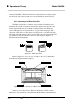
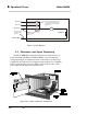
1.7 Rear Panel (Equipment Interface)
The rear panel, shown in Figure 1-2, contains the gas and electrical
connectors for external inlets and outlets. The Zero and Span gas connec-
tors, and the Current signal outputs are optional and may not appear on
your instrument. The connectors are described briefly here and in detail in
the Installation chapter of this manual.
Figure 1-2: Model 3000PA Rear Panel
• Power Connection Universal AC power source.
• Gas Inlet and Outlet One inlet (must be externally valved)
and one exhaust out. Three inlets when
“C” option is ordered.
• 9-Pin RS-232 Port Serial digital concentration signal
output and control input.
• 50-Pin Equipment Interface Port