
Instruction Manual

2-8
2 Operational Theory Model 3000PA
Teledyne Analytical Instruments
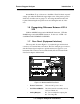
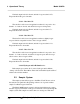
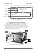
Figure 2-5: Flow Diagram
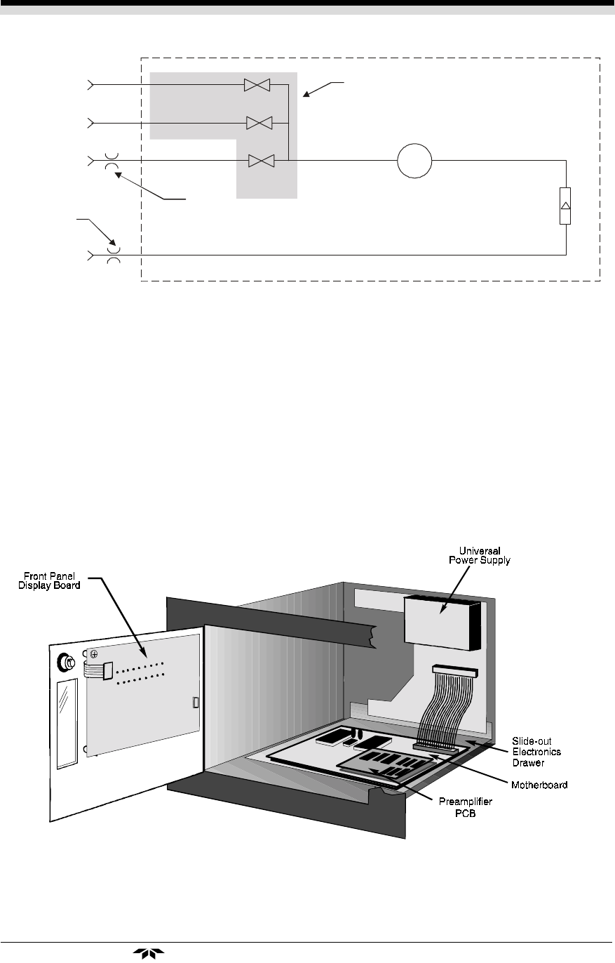
2.4 Electronics and Signal Processing
The Model 3000P Percent Oxygen Analyzer uses an 8031 microcon-
troller with 32 kB of RAM and 128 kB of ROM to control all signal pro-
cessing, input/output, and display functions for the analyzer. System power
is supplied from a universal power supply module designed to be compatible
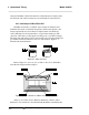
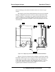
with any international power source. Figure 2-6 shows the location of the
power supply and the main electronic PC boards.
Figure 2-6: Location of Electronic Components
In vacuum service the
restrictor should be
placed here .
Sample In
Span In
Zero In
Flowmeter
Exhaust Out
Solenoid
Valves
Restrictor
Cell
In normal service the
restrictor should be
placed here .
Components in the shaded area are in
the -C option (internal control valves)
only and are not shown in the piping
diagram above.