OPERATING INSTRUCTIONS FOR Model 2120XL Trace Nitrogen in Argon Analyzer P/N M84744 11-27-13 DANGER This instrument is for analyzing nitrogen in argon only. Do not introduce any flammable or toxic gases into this instrument. Hazardous voltages exist on certain components internally which may be lethal. Disconnect power before servicing. Only authorized personnel should conduct maintenance and/or servicing. Before conducting any maintenance or servicing, consult with authorized supervisor/manager.
Model 2120XL Copyright © 2013 Teledyne Analytical Instruments All Rights Reserved. No part of this manual may be reproduced, transmitted, transcribed, stored in a retrieval system, or translated into any other language or computer language in whole or in part, in any form or by any means, whether it be electronic, mechanical, magnetic, optical, manual, or otherwise, without the prior written consent of Teledyne Analytical Instruments, 16830 Chestnut Street, City of Industry, CA 91748.
Trace Nitrogen in Argon Analyzer Specific Model Information This instrument relies on the known spectrum emitted from a plasma discharge from a distinct gas mixture of variable composition at or near atmospheric pressure. This instrument cannot be used for analysis on any gas or gas mixture other than nitrogen in argon or a mixture specified at the time of purchase. Specific filters carefully chosen and tested at the factory have been installed for the particular gas mixture.
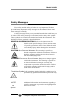
Model 2120XL Safety Messages Your safety and the safety of others is very important. We have provided many important safety messages in this manual. Please read these messages carefully. A safety message alerts you to potential hazards that could hurt you or others. Each safety message is associated with a safety alert symbol. These symbols are found in the manual and inside the instrument.
Trace Nitrogen in Argon Analyzer CAUTION: THE ANALYZER SHOULD ONLY BE USED ONLY FOR THE PURPOSE AND IN THE MANNER DESCRIBED IN THIS MANUAL. IF YOU USE THE ANALYZER IN A MANNER OTHER THAN THAT FOR WHICH IT WAS INTENDED, UNPREDICTABLE BEHAVIOR COULD RESULT POSSIBLY ACCOMPANIED WITH HAZARDOUS CONSEQUENCES. This manual provides information designed to guide you through the installation, calibration operation and maintenance of your new analyzer. Please read this manual and keep it available.
Model 2120XL Table of Contents List of Figures ................................................................ ix List of Tables .................................................................. x Introduction..................................................................... 1 1.1 Overview 1.2 Typical Applications 1.3 Features 1.4 Front Panel 1.5 Rear Panel 1.6 Internal Components 1.7 Additional Safety Information 1.7.1 Detector Cautions 1.7.2 Basic Safety Requirements 1.7.3 Precautionary Labels 1.7.
Trace Nitrogen in Argon Analyzer 3.2 Choosing a Location 3.3 Mounting 3.4 Rear Panel Connections 3.5 Electrical Connections 3.5.1 Primary Input Power 3.5.2 50-Pin Equipment Interface Connector 3.5.3 RS-232 Port 3.6 Gas Connections 3.6.1 Typical Sample System 3.6.2 Gas Connections to the Instrument 3.7 Purging 3.8 Calibration 3.9 Installation Checklist 18 18 19 20 20 20 26 27 29 31 31 33 33 Operation....................................................................... 35 4.1 Powering Up the Analyzer 4.
Model 2120XL 4.5.2 The Zero and Span Functions 4.5.2.1 Before Calibration 4.5.2.2 Recommended Calibration Gases 4.5.2.3 Zero Cal 4.5.2.4 Span Calibration 4.5.3 The Range Function 4.5.4 The Alarms Function 4.6 The Analyze Function 4.7 Signal Output 54 54 55 55 57 59 60 62 62 Maintenance .................................................................. 65 5.1 Routine Maintenance 5.2 Routine Maintenance Schedule 5.3 Fuse Replacement 5.4 System Self Diagnostic Test 5.5 Error Screens 5.
Trace Nitrogen in Argon Analyzer List of Figures Figure 1-1 Model 2120XL Front Panel Figure 1-2: Model 2120XL Rear Panel Figure 1-3: Internal Component Identification Figure 3-1: Required Front Door Clearance Figure 3-2: Rear Panel of the Model 2120XL Figure 3-3: Equipment Interface Connector Pin Arrangement Figure 3-4: Remote Valve Connections Figure 3-5: FET Series Resistance Figure 3-6: Suggested Sample System Figure 4-1: Hierarchy of Functions and Sub Functions Figure 5-1: Removing Fuse Block from Hous
Model 2120XL List of Tables Table 3-1: Analog Output Connections Table 3-2: Alarm Relay Contact Pins Table 3-3: Remote Calibration Connections Table 3-4: Range ID Relay Connections Table 3-5: Commands via RS-232 Input Table 3-6: Required RS-232 Options Table 5-1: Routine Maintenance Schedule Teledyne Analytical Instruments 21 22 23 24 26 27 66 x
Trace Nitrogen in Argon Analyzer DANGER COMBUSTIBLE GAS USAGE WARNING This is a general purpose instrument designed for use in a non-hazardous area. It is the customer's responsibility to ensure safety especially when combustible gases are present since the potential of gas leaks always exist. Never introduce gases other than argon into the analyzer. If explosive, flammable or corrosive gases or gas mixtures are allowed to flow into the analyzer, fire or explosion can result.
Model 2120XL Teledyne Analytical Instruments xii
Trace Nitrogen in Argon Analyzer Introduction Introduction 1.1 Overview This manual describes installation, operation and maintenance for the Model 2120XL Trace Nitrogen in Argon Gas Analyzer. Section 1 describes the analyzer in general terms and provides additional safety information pertinent to the proper operation of the instrument. The Teledyne Model 2120XL Trace Nitrogen in Argon Gas Analyzer is a robust analytical tool for measuring trace amounts of nitrogen in argon.
Introduction Model 2120XL Quality Control for Truck Fills & Gas Cylinders Process Control New Line Certification Chemical Plants Welding Gas Management Semiconductor Manufacturing 1.3 Features The Model 2120XL comes equipped with the following standard features: A 2-line alphanumeric vacuum fluorescent display (VFD) screen, driven by microprocessor electronics that continuously prompts and informs the operator.
Trace Nitrogen in Argon Analyzer Introduction Extensive self-diagnostic testing, at startup and on demand, with continuous power-supply monitoring. Two way RFI protection. RS-232 serial digital port for use with a computer or other digital communication device. Four analog outputs: two for measurement (0–1 VDC and isolated 4–20 mA DC) and two for range identification. Convenient and versatile, steel, flush-panel or rackmountable case with slide-out electronics drawer. 1.
Introduction Model 2120XL Function Keys: Six touch-sensitive membrane switches are used to change the specific function performed by the analyzer: Analyze Perform analysis for nitrogen content in an argon gas mixture. System Perform system-related tasks (described in detail in Chapter 4, Operation.). Span Span calibrate the analyzer. Zero Zero calibrate the analyzer. Alarms Set the alarm setpoints and attributes. Range Set up the 3 user definable ranges for the instrument.
Trace Nitrogen in Argon Analyzer Introduction Standby Button: The Standby turns off the display and outputs, but circuitry is still operating. CAUTION: THE POWER CABLE MUST BE UNPLUGGED TO FULLY DISCONNECT POWER FROM THE INSTRUMENT. WHEN CHASSIS IS EXPOSED OR WHEN ACCESS DOOR IS OPEN AND POWER CABLE IS CONNECTED, USE EXTRA CARE TO AVOID CONTACT WITH LIVE ELECTRICAL CIRCUITS .
Introduction Model 2120XL Calibration Contact Notifies external equipment that instrument is being calibrated and readings are not monitoring sample. Range ID Contacts Four separate, dedicated, range relay contacts. Low, Medium, High, Cal (not used). RS-232 Port Serial digital concentration signal output and control input. Gas Inlet and Outlet One inlet and one vent. Purge Connections Inlet and outlet connections for purging the analyzer.
Trace Nitrogen in Argon Analyzer Introduction and identifies specific components of the analyzer. See also Figure 1-4 for internal components inside the card cage. Figure 1-3: Internal Component Identification WARNING: HIGH VOLTAGE. ELECTROCUTION HAZARD. UNPLUG THE ANALYZER BEFORE REMOVING THE COVER. THE OUTPUT OF THE HIGH-VOLTAGE TRANSFORMER AND THE ANALYTICAL CELL ELECTRODES CAN APPROACH VOLTAGES OF 10,000 VAC. THE ANALYZER SHOULD BE SERVICED ONLY BY A QUALIFIED SERVICE TECHNICIAN. 1.
Introduction Model 2120XL Do NOT operate the Model 2120XL Trace Nitrogen in Argon Gas Analyzer until you read and understand the operating, maintenance, and safety instructions included in this manual. Anyone involved with the operation of this equipment including plant engineering, operations, and management, must understand the potential hazards involved, and know and observe all required safety precautions.
Trace Nitrogen in Argon Analyzer Introduction Since the cell is made of thin quartz, this analyzer must be used at atmospheric pressure to avoid cell damage. Any back pressure in the detector will cause damage and require replacement of the module. Make sure the vent is at atmospheric pressure and without restrictions or blockage. 1.7.
Introduction Model 2120XL 1.7.4 Summary of Known Hazards This equipment is designed to minimize your exposure to the process gases and other known hazards. Read and thoroughly understand all safety aspects of this system and its operation before operating or maintaining the equipment. 1.7.4.1 ELECTROCUTION WARNING: DO NOT OPERATE THE ANALYZER WITHOUT THE COVER SECURED IN PLACE. THE OUTPUT OF THE HIGH-VOLTAGE TRANSFORMER AND THE ANALYTICAL CELL ELECTRODES CAN APPROACH VOLTAGES OF 6,000 VAC OR HIGHER.
Trace Nitrogen in Argon Analyzer Introduction regulation. Read and understand the MSDSs for the process gases used before operating this analyzer. More detailed information on the precautions and safe practices to follow when handling cylinders can be found in the CGA pamphlet P-1, Safe Handling of Compressed Gases in Cylinders. 1.7.4.3 PURGING CAUTION: EQUIPMENT DAMAGE MAY RESULT IF THE ANALYTICAL CELL IN THIS UNIT IS EXPOSED TO PRESSURE ABOVE ATMOSPHERIC PRESSURE. THE CELL MAY BREAK OR SHATTER.
Introduction Model 2120XL not followed. Therefore, during handling and use of these gases, be certain to use applicable safety precautions described by your local compressed gas supplier, the Compressed Gas Association, and/or OSHA regulations. 1. Read the label on all cylinders BEFORE using to identify the cylinder contents. If the label is illegible, return the cylinder to the supplier. DO NOT ASSUME THE CONTENTS. 2.
Trace Nitrogen in Argon Analyzer Operational Theory Operational Theory 2.1 The Analyzer The Model 2120XL Trace Nitrogen in Argon Gas Analyzer is a rack mounting self-contained unit for measuring trace amounts of nitrogen in an argon gas stream. A customer supplied sample system directs a stream of refined argon to the instrument at a pressure between 4 and 20 psig (14-138 kPa).
Operational Theory Model 2120XL After analysis, the gas is returned to the gas flow module. A signal is produced in the flow transducer that is used by the microprocessor to control the flow control valve. From the flow control module, the gas exits the analyzer at atmospheric pressure. The superior accuracy of the Model 2120XL is achieved through enhanced coupling of the plasma to the process and an advanced plasma generator design.
Trace Nitrogen in Argon Analyzer CAUTION: Operational Theory IT IS THE RESPONSIBILITY OF THE END USER TO PROVIDE A SUITABLE SAMPLE SYSTEM CAPABLE OF DELIVERING CLEAN, PARTICULATE-FREE ARGON THAT IS AIR AND MOISTURE FREE. EQUIPMENT DAMAGE MAY RESULT IF THE ANALYTICAL CELL IN THIS UNIT IS EXPOSED TO PRESSURE, CAUSING IT TO BREAK OR SHATTER. TO PREVENT THIS, NEVER EXCEED 20 PSIG (138 KPA) ON THE INPUT PORT AND ALWAYS MAINTAIN THE VENT AT ATMOSPHERIC PRESSURE. DO NOT BLOCK THE VENT.
Operational Theory Teledyne Analytical Instruments Model 2120XL 16
Trace Nitrogen in Argon Analyzer Installation Installation Installation of the Model 2120XL Trace Nitrogen in Argon Analyzer can involve potentially hazardous procedures. CAUTION: INSTALLATION SHOULD BE PERFORMED ONLY BY TRAINED AND QUALIFIED PERSONNEL WHO HAVE READ AND UNDERSTOOD THE INSTRUCTIONS IN THIS MANUAL.
Installation Model 2120XL 3.2 Choosing a Location Locate the Model 2120XL in a clean area free of: Excessive dust Mechanical vibrations Strong electric or electromagnetic fields Corrosive gases Moisture exceeding 90% relative humidity The use of walkie-talkies or cellular phones Choose a location where sudden temperature changes in excess of 5°F (5°C) do not occur and where the temperature does not exceed the specified ambient temperature range.
Trace Nitrogen in Argon Analyzer Installation Figure 3-1: Required Front Door Clearance 3.4 Rear Panel Connections Figure 3-2 shows the Model 2120XL rear panel. Up to 7 gas inlet and outlet ports are installed depending on whether the unit is supplied with an optional auto calibration module.
Installation Model 2120XL 3.5 Electrical Connections Electrical Connections are made at the rear of the instrument. See Figure 3-2. For safe connections, no uninsulated wiring should be able to come in contact with fingers, tools or clothing during normal operation. CAUTION: USE SHIELDED CABLES. ALSO, USE PLUGS THAT PROVIDE EXCELLENT EMI/RFI PROTECTION. THE PLUG CASE MUST BE CONNECTED TO THE CABLE SHIELD, AND IT MUST BE TIGHTLY FASTENED TO THE ANALYZER WITH ITS FASTENING SCREWS.
Trace Nitrogen in Argon Analyzer Installation Figure 3-3: Equipment Interface Connector Pin Arrangement Analog Outputs: There are four DC output signal pins—two pins per output. For polarity, see Table 3-1. The outputs are: 0–1 VDC % of Range: Voltage rises linearly with increasing oxygen, from 0 V at 0 ppm to 1 V at full scale ppm. (Full scale = 100% of programmable range.) 0–1 VDC Range ID: 0.25 V = Low Range, 0.5 V = Medium Range, 0.75 V = High Range, 1 V = 100ppm.
Installation Model 2120XL Alarm Relays: The nine alarm-circuit connector pins connect to the internal alarm relay contacts. Each set of three pins provides one set of Form C relay contacts. Each relay has both normally open and normally closed contact connections. The contact connections are shown in Table 3-2. They are capable of switching up to 3 amperes at 250 VAC into a resistive load.
Trace Nitrogen in Argon Analyzer Installation Digital Remote Cal Inputs: Accept 0 V (off) or 24 VDC (on) inputs for remote control of calibration. (See Remote Calibration Protocol below.) See Table 3-3 for pin connections. Zero: Floating input. 5 to 24 V input across the + and – pins puts the analyzer into the Zero mode. Either side may be grounded at the source of the signal. 0 to 1 volt across the terminals allows Zero mode to terminate when done.
Installation Model 2120XL When the contact is CLOSED, the analyzer is already calibrating. It will ignore your request to calibrate, and it will not remember that request. Once a zero or span command is sent, and acknowledged (contact closes), release it. If the command is continued until after the zero or span is complete, the calibration will repeat and the Cal Relay Contact (CRC) will close again. For example: 1. Test the CRC.
Trace Nitrogen in Argon Analyzer 18 Range 3 ID Contact 34 Range 4 ID Contact (not used) 35 Range 4 ID Contact (not used) Installation Network I/O: A serial digital input/output for local network protocol. At this printing, this port is not yet functional. It is to be used for future options to the instrument. Pins 13 (+) and 29 (–). Remote Valve Connections: The Model 2120XL is a single-chassis instrument and does not have a Remote Probe.
Installation Model 2120XL Figure 3-5: FET Series Resistance 3.5.3 RS-232 Port The digital signal output is a standard, full duplex RS-232 serial communications port used to connect the analyzer to a computer, terminal, or other digital device. It requires a standard 9-pin D connector. The output data is status information, in digital form, updated every two seconds.
Trace Nitrogen in Argon Analyzer Installation az Immediately starts an autozero. st Toggling input. Stops/Starts any status message output from the RS-232, until st is sent again. The RS-232 protocol allows some flexibility in its implementation. Table 3-6 lists certain RS-232 values that are required by the Model 2120XL implementation. Table 3-6: Required RS-232 Options Parameter Setting Baud 9600 Byte 8 bits Parity none Stop Bits Message Interval 1 2 seconds.
Installation Model 2120XL Note: Air leaking into the sampling system will cause erratic or unsatisfactory analyzer operation. Even if air is admitted into the system for only a few minutes, you must purge the regulator and the system for at least 1 hour before the readings stabilize. See Section 3.7. Whenever a fitting on the sample system is opened, use a new ferrule and cone or new gasket depending on the type of fitting to secure a gas tight seal.
Trace Nitrogen in Argon Analyzer CAUTION: Installation AIR PRESSURE LESS THAN 65 PSIG WILL RESULT IN A FLOW RESTRICTION. 4. Connect the span and zero lines to the rear panel fittings supplied for this purpose. The span and zero gas inputs must be pressure regulated to the same pressure as the sample gas (4-20 psig). Note: If this instrument is without the auto calibration option, there will be no rear panel fittings for zero and span gases.
Installation Model 2120XL The sample manifold system must be designed so that you can: Purge the sample line and pre-adjust the flow rate before admitting a sample to the analytical cell. Maintain a flow of argon through the analytical cell whenever ionization voltage is being applied.
Trace Nitrogen in Argon Analyzer Installation 3.6.2 Gas Connections to the Instrument CAUTION: EQUIPMENT DAMAGE MAY RESULT IF THE ANALYTICAL CELL IN THIS UNIT IS EXPOSED TO PRESSURE ABOVE ATMOSPHERIC, CAUSING IT TO BREAK OR SHATTER. TO PREVENT THIS, NEVER EXCEED 20 PSIG (138 KPA) ON THE INLET PORT. ALWAYS ENSURE THAT THE VENT IS AT ATMOSPHERIC PRESSURE. DO NOT REMOVE THE FLOW CONTROL ORIFICE FROM THE SAMPLE INLET OF THE ANALYZER. DO NOT BLOCK THE VENT. To connect the gas line: 1.
Installation Model 2120XL When installing a new analyzer or starting up an analyzer that has been idle for a period of time, the sampling system should be purged for several hours to cleanse it of contaminants and water vapor. Although high-purity sample gas may be used to purge the analyzer, argon with a minimum purity of 99.999% is recommended. The exact purge method depends on the sample manifold design and construction. In general, each sample inlet line must be thoroughly purged.
Trace Nitrogen in Argon Analyzer Installation 3.8 Calibration The Model 2120XL was calibrated at the factory in accordance with the calibration data shipped with your instrument. Prior to using the instrument for analysis the calibration must be checked using the factory settings supplied. If the settings do not match, the instrument should be recalibrated prior to using for the first time.
Installation Model 2120XL Teledyne Analytical Instruments 34
Trace Nitrogen in Argon Analyzer Operation Operation This section describes the operation and calibration procedures for the Model 2120XL Trace Nitrogen in Argon Analyzer. Operation of the analyzer involves potentially hazardous procedures. Only trained and qualified personnel who have read and understood the instructions in this manual should operate this equipment. CAUTION: DO NOT OPERATE THIS ANALYZER UNTIL YOU HAVE READ AND UNDERSTOOD THE INSTRUCTIONS IN THIS MANUAL.
Operation Model 2120XL 4.1 Powering Up the Analyzer CAUTION: OZONE EMISSIONS ARE POSSIBLE IF AIR OR MOISTURE ARE IONIZED IN THE SAMPLING SYSTEM. THE SAMPLE PATH MUST BE RELATIVELY FREE OF AIR AND/OR MOISTURE BEFORE APPLYING THE IONIZING VOLTAGE. KEEP THE POWER OFF UNTIL THE ANALYZER IS FULLY PURGED. 1. Purge the analyzer and sampling system using the procedure described in Section 3.7. 2. Connect the power cord to the proper power source for your analyzer.
Trace Nitrogen in Argon Analyzer Operation 4.3 Setup and Operation General Information Once the analyzer has been installed, it can be configured for your application. To do this you will: Set system parameters: Establish a security password, if desired, requiring Operator to log in. Establish and start an automatic calibration cycle, if desired. Calibrate the instrument. Define the three user selectable analysis ranges. Then choose auto ranging or select a fixed range of analysis, as required.
Operation Model 2120XL VFD screen that are not yet accepted by use of the ENTER key or to move backwards through previous screens. The VFD screen text that accompanies each operation is reproduced, at the appropriate point in the procedure, in a Arial Narrow Bold type style. The various operational modes are printed in CAPITALIZED ITALICS. Figure 4-1 shows the hierarchy of functions available to the operator via the screen menus.
Trace Nitrogen in Argon Analyzer Operation Figure 4-1: Hierarchy of Functions and Sub Functions 4.5.1 System Menu Dig_filt Self-test Pwd Logout Err More . . Autocal Flow Hold Calholdtimer More . Model Out-cal Lin There are eleven sub functions within the System function as described below. Specific procedures for their use follow the descriptions.
Operation Model 2120XL Dig Filt: The Model 2120XL includes a user adjustable digital filter. The filter has settings 1-10. Setting 1 is the least amount of filtering and 10 is the highest level of damping. Self–Test: The instrument performs a self-diagnostic test to check the integrity of the power supply, output boards and amplifiers. PSWD: Security can be established by choosing a 5 digit password (PSWD) from the standard ASCII character set.
Trace Nitrogen in Argon Analyzer Operation Weight of Digital Filter: 4 The current filter setting (4 in this case) will be flashing. It can be modified from 0 (no filtering) to 10 maximum filtering using the ▲/▼ keys. Pressing ENTER will accept the value and return to the SYSTEM menu. The default setting should suffice for most applications. In some applications where speeding the response time with some trade off in noise is of value, the operator could decrease the number of the digital filter.
Operation Model 2120XL indicates a problem in a specific area of the instrument. Refer to Chapter 5 Maintenance and Troubleshooting for number-code information. The results screen alternates for a time with: Press Any Key To Continue... Then the analyzer returns to the initial System screen. 4.5.1.3 PASSWORD PROTECTION Security can be established by choosing a 3 digit password (PSWD) from the standard ASCII character set.
Trace Nitrogen in Argon Analyzer Operation the microprocessor. The operator just presses the Enter key to be allowed total access to the instrument’s features. Note: If you use password security, it is advisable to keep a copy of the password in a separate, safe location. 4.5.1.3.1 Entering the Password To install a new password or change a previously installed password, you must key in and ENTER the old password first.
Operation Model 2120XL Change Password? =Yes =No Press ESCAPE to move on, or proceed as in Changing the Password, below. 4.5.1.3.2 Installing or Changing the Password If you want to install a password, or change an existing password, proceed as above in Entering the Password.
Trace Nitrogen in Argon Analyzer s } ) 3 = t → * 4 > u ! + 5 ? v " ' 6 @ w # 7 Operation x $ . 8 y % / 9 z & 0 : { ' 1 ; | ( 2 < When you have finished typing the new password, press Enter. A verification screen appears. The screen will prompt you to retype your password for verification. Confirm Pwd: ‘ A A A’ Retyping the password will confirm proper password is entered and the following screen will appear briefly: New Pwd Accepted and then return to the System menu.
Operation Model 2120XL 4.5.1.4 LOGOUT The Logout function provides a convenient means of leaving the analyzer in a password protected mode without having to shut the instrument off. By entering Logout, you effectively log off the instrument leaving the system protected against use until the password is reentered. To log out, press the System button to enter the System function.
Trace Nitrogen in Argon Analyzer Neg. Flow Adc Error Bad Adc Channel Sel. Bad Gain Selected Zero Fail Span Fail Sys Test - - 5V Sys Test - - 15V Sys Test - - Dac A Sys Test - - Dac B Sys Test - - Preamp 0.0V Sys Test - - Preamp 0.7V Sys Test - - Pre Gain Ck Operation See Section 5.5 for additional information on error screens. 4.5.1.
Operation Model 2120XL Model 2120XL is accurate to 2-3 %. Accordingly, internally scheduled calibrations can vary 2-3 % per day. To setup an Auto Cal cycle: Choose SYSTEM from the function buttons. Use the ◄►arrow keys to position the blinking over the More function, and press ENTER. A second display of System functions will appear. Use the ◄►arrow keys again to position the blinking over the Auto Cal function, and press ENTER to enter the function.
Trace Nitrogen in Argon Analyzer Operation If instrument is turned off, the next time the instrument is powered, the instrument will automatically perform a calibration cycle after 3 minutes of entering the sample mode if AUTO CAL functions were on prior to shut down. 4.5.1.7 FLOW This function allows the user to set the flowrate through the flow control valve. The first line of the display indicates the current flow setting in ccm and can be manipulated using the ▲/▼ arrow keys.
Operation Model 2120XL When HOLD is selected, the analog output (4-20 mA) and the range ID contacts will freeze on their last state before entering one of the calibration modes. When the instrument returns to the Analyze mode, either by a successful or an aborted calibration, there will be a threeminute delay before the analog outputs and the range ID contacts start tracking again. The concentration alarms freeze on their last state before entering calibration regardless of selecting HOLD or TRACK.
Trace Nitrogen in Argon Analyzer Operation the above to ENTER at More a second time. This will display a third screen of system functions as shown below. Model Out-cal Lin Use the ◄►arrow keys to position the blinking over the Model function, and press ENTER to display your specific Model information. 4.5.1.11 ANALOG OUTPUT CALIBRATION (OUT_CAL) For enhanced accuracy, this function allows the user to calibrate the 4 to 20 mA analog output to remove any offsets inherent in the PCB.
Operation Model 2120XL Repeat the process for adjusting the 20 mA output. Pressing ENTER will accept the value and return the display to the last System screen. 4.5.1.12 LINEARIZE (LIN) With this function, the user has the capability of linearizing the output of the instrument by flowing prepared samples with known concentration across the analytical range. The linearization can be performed manually or automatically depending on the setting chosen in the linearization setup screen.
Trace Nitrogen in Argon Analyzer Operation by the analyzer’s display. In Auto mode, this is done automatically by the software. From the Linearizer (Lin) function screen, use the ◄►arrow keys to position the blinking over the Setup function, and press ENTER. The following screen appears: Linearize Manual Auto To enter Manual or Auto Mode, use the ◄►arrow keys to position the blinking over the Manual or Auto and press ENTER. The following screen appears: In 0.0ppb Out 0.
Operation Model 2120XL polynomial once all data has been entered. The screen will return to the AUTO/MAN screen with the upper right number incremented by 1. If ESCAPE is pressed, the data will be rejected and the screen will return to the AUTO/MAN screen without incrementing the sample number in the right corner. Repeat the above procedures for each prepared linearization sample making sure to adequately flush or purge the lines each time a new sample is connected.
Trace Nitrogen in Argon Analyzer Operation regulator on the sample inlet. Do not exceed a maximum of 20 psig (138 kPa). 4.5.2.2 RECOMMENDED CALIBRATION GASES Teledyne recommends the following gases be used for calibration: Zero Gas: N2-free Ar Span Gas: For 0-1 ppm range: 0.7-1.0 ppm N2 in Ar For 0-10 ppm range: 7-10 ppm N2 in Ar For 0-100 ppm range: 70 – 100 ppm N2 in Ar (best for overall accuracy on all ranges) The first calibration point is fixed by a zero gas.
Operation Model 2120XL ▲/▼ arrow keys. Once the proper mode is displayed, press ENTER. The following screen appears: Zero Offset 0.0ppb to Begin This screen allows the user to add a zero offset if desired. With the value adjacent to Zero Offset blinking, use the ▲/▼ arrow keys to enter any offset required. Press ENTER when finished. 4.5.2.3.1 Manual Zero If manual zero mode was selected, the following screen appears: N2: 1.
Trace Nitrogen in Argon Analyzer Operation When the counter reaches zero, the display switches to display the gain on G1: Zero Settling: G1/11 Δ2.1 Val:-12345 where Δ Val:-12345 is a live display of the change in the adc. Shortly the display will change to a second screen representing the gain on G2: Zero Acquired G1/1 Δ-3.6 Val:-12345 Zero Acquired G01/1 Δ 0.6 Val:-12345 followed by: where the Δ Val:-12345 is the live display of the change in the adc for G01.
Operation Model 2120XL ▲/▼ arrow keys. Once the proper mode is displayed, press ENTER. The following screen appears: Span 100.0ppm to begin Span This screen allows the user to input the known concentration of the span gas used. Uuse the ▲/▼ arrow keys to enter the span gas concentration. Press ENTER when finished. 4.5.2.3.1 Manual Span If manual span mode was selected, the following screen appears: 39.
Trace Nitrogen in Argon Analyzer Operation 4.5.3 The Range Function The Model 2120XL has three user programmable ranges extending from 0-1 ppm to 0-100 ppm. The Range function is used to set the three analysis ranges and to set whether the instrument functions on a fixed range (1, 2 or 3) or uses auto ranging. To set the range properties for your instrument, press the RANGE button. The following screen appears: R1: 1.00ppm R2: 10.00ppm R3: 100.0ppm Rng: Auto where either the 1.00, 10.00, 100.
Operation Model 2120XL 4.5.4 The Alarms Function The Model 2120XL is equipped with 2 fully adjustable concentration alarms and one non-adjustable system alarm. Each alarm has a relay with a set of form “C" contacts rated for 3 amperes resistive load at 250 VAC. Refer to Chapter 3, Installation and/or the Interconnection Diagram included at the back of this manual for relay connections. The concentration alarms can be configured from the front panel as either high or low alarms by the operator.
Trace Nitrogen in Argon Analyzer Operation 4. Are either of the alarms to be defeated? The defeat alarm mode is incorporated into the alarm circuit so that maintenance can be performed under conditions which would normally activate the alarms. The defeat function can also be used to reset a latched alarm. (See procedures, below.) If you are using password protection, you will need to enter your password to access the alarm functions. Follow the instructions in Section 4.5.1.3 to enter your password.
Operation Model 2120XL To set the other parameters use the ◄►arrow keys to move the blinking over to the desired parameter. Then use the ▲/▼ arrow keys to change the parameter. Once the parameters for alarm 1 have been set, press Alarms again, and repeat this procedure for alarm 2 (AL2). To reset a latched alarm, go to Dft– and then press either ▲ two times or ▼ two times to toggle Dft from Y and then back to N. –OR – Go to Ltch– and then press either ▲ two times or ▼ two times.
Trace Nitrogen in Argon Analyzer 70 80 90 100 0.7 0.8 0.9 1.0 Operation 15.2 16.8 18.4 20.0 The analog output signal has a voltage which depends on the nitrogen concentration AND the currently activated analysis range. To relate the signal output to the actual concentration, it is necessary to know what range the instrument is currently on, especially when the analyzer is in the auto-ranging mode. To provide an indication of the range, a second pair of analog output terminals are used.
Operation Model 2120XL Teledyne Analytical Instruments 64
Trace Nitrogen in Argon Analyzer Maintenance Maintenance CAUTION: MAINTENANCE AND REPAIR OF THE MODEL 2120XL ANALYZER INVOLVE POTENTIALLY HAZARDOUS PROCEDURES. ONLY TRAINED AND QUALIFIED PERSONNEL WHO HAVE READ AND UNDERSTOOD THE INSTRUCTIONS IN THIS MANUAL SHOULD WORK ON THIS EQUIPMENT. 5.1 Routine Maintenance Aside from normal cleaning and checking for leaks at the gas connections, routine maintenance consists of recalibration and periodic inspection of essential analyzer parts.
Maintenance Model 2120XL Table 5-1 summarizes the recommended routine maintenance required for the Model 2120XL. Table 5-1: Routine Maintenance Schedule Maintenance Task Time Schedule Calibrate Every 1-2 weeks Check sample gas flow rate Every 1-2 weeks Check for excessive accumulation of dirt Weekly Check gas lines for leaks Yearly 5.3 Fuse Replacement 1. Place small screwdriver in notch, and pry cover off, as shown in Figure 5-1. Figure 5-1: Removing Fuse Block from Housing 2.
Trace Nitrogen in Argon Analyzer American Fuses Maintenance European Fuses Figure 5-2: Installing Fuses 5.4 System Self Diagnostic Test 1. Press the System button to enter the system mode. 2. Use the ◄► arrow keys to move to More, and press Enter. 3. Use the ◄► arrow keys to move to Self-Test, and press Enter.
Maintenance Model 2120XL 5.5 Error Screens Additional errors are indicated by a flashing ‘E’ at the upper right corner of the analyzer display screen. If 'E' is flashing in the upper right hand corner, the instrument has detected an error. Go to menu item 'Err' and press ENTER. If there are errors, they will be listed on the screen'. Use the UP/DOWN to scroll through the errors. Press ENTER to dispatch the current error. If the error condition still persists, the flashing ‘E’ will return.
Trace Nitrogen in Argon Analyzer Maintenance "Sys Test -- 5V " The system test on the 5V power supply has found a problem. SysTest15V 0x0100 "Sys Test -- 15V " The system test on the 15V power supply has found a problem. SysTest Analog 1 0x0200 "Sys Test DAC A " The system test on analog channel 1 (% of range) is incorrect. SysTest Analog 2 0x0400 "Sys Test DAC B " The system test on analog channel 2 (Range ID) is incorrect SysTestPreamp_0_0V 0x0800 "Sys Test Preamp 0.
Maintenance Model 2120XL Teledyne Analytical Instruments 70
Trace Nitrogen in Argon Analyzer Appendix Appendix A.1 Specifications Detector: Plasma Emission Detector with Duty Controlled System Measurement Ranges: 3 user programmable ranges from 0-1 ppm to 0-100 ppm. Output: 4-20 mA and 0-1 vdc, concentration and Range ID Sample Flowrate: adjustable 15-200 sccm, 100 ccm default for optimal operation Zero Cal. Gas: Through Scrubber TAI P/N S1748 Span Cal.
Appendix Model 2120XL Digital Inputs: Two digital inputs for remote span and zero Weight: 35 lbs (15.9 kg) A.2 Recommended Replacement Parts List Qty. Part Number Description 1 C75825A Main PCB w/o EPROM 1 C84447A Amplifier PCB 1 C84132A Back Panel Power Supply PCB 1 C84129A Front Panel Display PCB 1 S01748-120 Scrubber of N2 Gas for zero cal. (120 V) -OR- 1 S01748-240 Scrubber of N2 Gas for zero cal. (240 V) 1 F2374 Flow Control Module 1 A85552 2120XL std.
Trace Nitrogen in Argon Analyzer Appendix A.