
Manual


Installation Model 2120
The sample manifold system must be designed so that you can:
• Purge the sample line and pre-adjust the flow rate before
admitting a sample to the analytical cell.
• Maintain a flow of argon through the analytical cell whenever
ionization voltage is being applied.
The following guidelines are presented as an aid in constructing a
suitable external sampling system for the Model 2120:
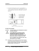
• Alter the geometry of the system in Figure 3-2, as necessary, to
suit your specific needs and to maintain access to items on the
rear panel. However, alterations should be adhered to
schematically.
• Use 1/8-inch (0.32 cm) electro polished stainless steel tubing for
all parts of the manifold between the source and sample inlet
connections of the analyzer. Although you can use 1/4-inch (0.64
cm) tubing, it is not recommended. The manifold should be a
welded assembly wherever possible.
• Use only high-purity components with metal seals.
• Eliminate excess components.
• Minimize "dead spaces" in the sample lines.
• Use a 1/4-inch (0.64 cm) VCR fitting for the analyzer inlet
connection. 1/4-in VCR glands with 1/8 in tube stubs are
available.
• Use a high-quality regulator or device to maintain a constant
pressure to the zero, sample, and span inlet lines. Teledyne
recommends using a high-purity regulator with the following
specifications:
• 2-stage tied diaphragm
• 100 psi outlet
• 15 RA max
• 5 ports
• CGA 580 welded on inlet side
• 1/4 MVCR (1 port), 1/4 FVCR (1 port)
• 2 gauges
24 Teledyne Analytical Instruments