OPERATING INSTRUCTIONS FOR Model 2120 Trace Nitrogen in Argon Analyzer P/N MXXXX ECO: DANGER This instrument is for analyzing nitrogen in argon only. Do not introduce any flammable or toxic gases into this instrument. Hazardous voltages exist on certain components internally which may be lethal. Disconnect power before servicing. Only authorized personnel should conduct maintenance and/or servicing. Before conducting any maintenance or servicing, consult with authorized supervisor/manager.
Model 2120 Copyright © 2006 Teledyne Analytical Instruments All Rights Reserved. No part of this manual may be reproduced, transmitted, transcribed, stored in a retrieval system, or translated into any other language or computer language in whole or in part, in any form or by any means, whether it be electronic, mechanical, magnetic, optical, manual, or otherwise, without the prior written consent of Teledyne Analytical Instruments, 16830 Chestnut Street, City of Industry, CA 91749-1580.
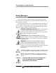
Trace Nitrogen in Argon Analyzer Safety Messages Your safety and the safety of others is very important. We have provided many important safety messages in this manual. Please read these messages carefully. A safety message alerts you to potential hazards that could hurt you or others. Each safety message is associated with a safety alert symbol. These symbols are found in the manual and inside the instrument.
Model 2120 IF YOU USE THE ANALYZER IN A MANNER OTHER THAN THAT FOR WHICH IT WAS INTENDED, UNPREDICTABLE BEHAVIOR COULD RESULT POSSIBLY ACCOMPANIED WITH HAZARDOUS CONSEQUENCES. This manual provides information designed to guide you through the installation, calibration operation and maintenance of your new analyzer. Please read this manual and keep it available. Occasionally, some instruments are customized for a particular application or features and/or options added per customer requests.
Trace Nitrogen in Argon Analyzer Table of Contents List of Figures............................................................................. viii List of Tables ................................................................................ ix Introduction ................................................................................... 1 1.1 Overview 1 1.2 Typical Applications 1 1.3 Features 2 1.4 Front Panel 3 1.5 Rear Panel 4 1.6 Internal Components 6 1.7 Additional Safety Information 8 1.7.
Model 2120 3.2 Choosing a Location 3.3 Mounting 3.4 Electrical Connections 3.5 Gas Connections 3.5.1 Typical Sample System 3.5.2 Gas Connections to the Instrument 3.6 Purging 3.7 Calibration 3.8 Installation Checklist 20 20 21 22 23 25 25 26 27 Operation ..................................................................................... 29 4.1 Powering Up the Analyzer 30 4.2 Zero and Span Calibration 31 4.2.1 Before Calibration 31 4.2.2 Recommended Calibration Gases 31 4.2.3 Calibration Steps 32 4.
Trace Nitrogen in Argon Analyzer 5.4.11 Low Voltage DC Supply Board 5.4.12 Regulated 255 Hz Power Supply 5.4.13 Digital Panel Meter 5.4.14 Zero and Span Potentiometers 49 49 49 50 Appendix ...................................................................................... 51 A.1 Specifications 51 A.2 Recommended Replacement Parts List 52 A.3 Sample Equipment Calibration Log Form 53 Index .............................................................................................
Model 2120 List of Figures Figure 1-1 Model 2120 Front Panel................................................. 3 Figure 1-2: Model 2120 Rear Panel ................................................ 5 Figure 1-3: Internal Component Identification ................................. 6 Figure 1-4: Internal Components in Card Cage............................... 8 Figure 2-1 Block Diagram for the Model 2120 Analyzer ................ 16 Figure 3-1: Analyzer Dimensions ................................................
Trace Nitrogen in Argon Analyzer List of Tables Table 5-1: Routine Maintenance Schedule.................................... 38 Table 5-2: Troubleshooting............................................................
Model 2120 DANGER COMBUSTIBLE GAS USAGE WARNING This is a general purpose instrument designed for use in a non-hazardous area. It is the customer's responsibility to ensure safety especially when combustible gases are present since the potential of gas leaks always exist. Never introduce gases other than argon into the analyzer. If explosive, flammable, or corrosive gases or gas mixtures are allowed to flow into the analyzer, fire or explosion can result.
Trace Nitrogen in Argon Analyzer Introduction Introduction 1.1 Overview This manual describes installation, operation and maintenance for the Model 2120 Trace Nitrogen in Argon Gas Analyzer. Section 1 describes the analyzer in general terms and provides additional safety information pertinent to the proper operation of the instrument. The Teledyne Model 2120 Trace Nitrogen in Argon Gas Analyzer is a robust analytical tool for measuring trace amounts of nitrogen in argon.
Introduction Model 2120 • Specialty Gas Laboratories • Specialty Steel Manufacturing • Gas Management/Monitoring Systems • Quality Control for Truck Fills & Gas Cylinders • Process Control • New Line Certification • Chemical Plants • Welding Gas Management • Semiconductor Manufacturing 1.3 Features The Model 2120 comes equipped with the following standard features: 2 • Digital Panel Meter—convenient and immediate display of the current sample analysis.
Trace Nitrogen in Argon Analyzer • Introduction Low Flow Switch—cuts power to the ionizer if the sample flow falls below a setpoint. 1.4 Front Panel Operator controls and displays are located on the front panel as shown in Figure 1-1. Figure 1-1 Model 2120 Front Panel • Status Indicator Lights: • Ionizer Light —Illuminates when the 255 Hz power supply is operational and its output is being supplied to the switching relay. • Power Light— Illuminates when main power switch is on and the fuse is good.
Introduction CAUTION: Model 2120 THE DISPLAY METER INDICATES A LOW LEVEL IMPURITY ANALYSIS WHILE IN THIS MODE. THIS IS NOT THE ACTUAL NITROGEN CONCENTRATION. • Range Switch: Used to select the measurement range maximum ppm. • Digital Panel Meter (DPM) — Displays the nitrogen content of the sample stream in ppm. Note: When there is no sample flow or there is a loss of ionization voltage, or when the impurities are out of range (i.e.
Trace Nitrogen in Argon Analyzer Introduction Figure 1-2: Model 2120 Rear Panel • Recorder Contacts — A standard barrier terminal connection is installed for connecting a recorder or other external meter to the analyzer. • Test Point Contacts —Provides an mVDC output signal connector for a DC multimeter and is used during calibration. • Overrange Alarm Contacts* — Normally open and normally closed dry contacts for indication of impurities at levels too high for analyzer's range of detection.
Introduction Model 2120 1.6 Internal Components The internal components can be accessed by removing the top cover of the analyzer. Figure 1-3 shows an inside view of the analyzer and identifies specific components of the analyzer. See also Figure 1-4 for internal components inside the card cage. Figure 1-3: Internal Component Identification WARNING: 6 HIGH VOLTAGE. ELECTROCUTION HAZARD. UNPLUG THE ANALYZER BEFORE REMOVING THE COVER.
Trace Nitrogen in Argon Analyzer Introduction The following list is keyed to Figure 1-3 and serves to identify and briefly describe the function of various internal components of the Model 2120 analyzer. 1. Card Cage for PCB's — Contains the amplifier board, 4-20 mA conversion board, test point jacks. The interface board is on rear of cage. 2. PMT Cover —Shields the PMT for noise reduction and protects it from atmospheric impurities. 3.
Introduction Model 2120 13. Low-Flow Switch — Works by magnetic levitation. When sample flow drops below the flow switch setpoint, the switch makes and pulls in the double-pole relay. 14. Rotameter Inlet and Outlet Connections — 114-in (0.64-cm) Swagelok compression fittings used to connect the sampling lines to the rotameter. 15. Zero and Span Potentiometers — Used for calibration with zero and span gas. 16.
Trace Nitrogen in Argon Analyzer Introduction maintenance, and safety instructions included in this manual. Anyone involved with the operation of this equipment including plant engineering, operations, and management, must understand the potential hazards involved, and know and observe all required safety precautions. Your safety and the safety of equipment, nearby facilities, and personnel require a proper safety attitude and emphasis on safe work procedures.
Introduction Model 2120 Ambulance: ___________ Fire Department: ___________ Sheriff or Police Department: ___________ On-Site Operations Representative: ___________ Training and education are the most important parts of any safety program. For every possible emergency, establish an Emergency Response Plan and maintain it for immediate use. 1.7.
Trace Nitrogen in Argon Analyzer Introduction Labels attached in appropriate areas of the analyzer warn you of inherent hazards associated with the system. For personal safety, read the labels and perform directed instructions before handling the equipment. 1.7.4 Summary of Known Hazards This equipment is designed to minimize your exposure to the process gases and other known hazards.
Introduction Model 2120 Sudden or uncontrolled release of pressurized gas can cause serious injury. The hazards of high pressure can be avoided through careful inspection and handling of cylinders and equipment with proper regulation. Read and understand the MSDSs for the process gases used before operating this analyzer. More detailed information on the precautions and safe practices to follow when handling cylinders can be found in the CGA pamphlet P-1, Safe Handling of Compressed Gases in Cylinders. 1.
Trace Nitrogen in Argon Analyzer Introduction Vent all pressure relief valves out of enclosed areas. Piping must be properly sized to allow safety devices to operate according to specifications. De-pressurize supply gas piping before working on it. 1.7.4.5 GENERAL PRECAUTIONS FOR HANDLING AND STORING HIGH PRESSURE GAS CYLINDERS Compressed gases have properties that can cause serious accidents, injuries, and even death if proper precautions and safety practices are not followed.
Introduction Model 2120 10. Never tamper with safety devices in valves or cylinders. 11. Do not store full and empty cylinders together. Serious suckback can occur when an empty cylinder is attached to a pressurized system. 12. No part of a cylinder should be subjected to a temperature higher than 52°C (125°F). Do not permit flame to come in contact with any part of a compressed gas cylinder.
Trace Nitrogen in Argon Analyzer Operational Theory Operational Theory 2.1 The Analyzer The Model 2120 Trace Nitrogen in Argon Gas Analyzer is a rack mountable self-contained unit for measuring trace amounts of nitrogen in an argon gas stream. A customer supplied sample system directs a stream of refined argon to the instrument at a pressure between 2 and 7 psig (14-48 kPa). The process stream enters at a constant flow rate and passes through a glass analytical cell to which metal electrodes are attached.
Operational Theory Model 2120 Figure 2-1 Block Diagram for the Model 2120 Analyzer 2.2 Overrange Protection If nitrogen content approaches 1000 ppm, the overall content of light from the plasma discharge decreases considerably. At about 2 percent nitrogen, the ionization is completely extinguished. This effect causes the PMT output to decrease; resulting in a signal that looks like no nitrogen is present in the argon sample, when in fact the content is greater than 1000 ppm.
Trace Nitrogen in Argon Analyzer CAUTION: Operational Theory IT IS THE RESPONSIBILITY OF THE END-USER TO PROVIDE A SUITABLE SAMPLE SYSTEM CAPABLE OF DELIVERING CLEAN, PARTICULATE-FREE ARGON THAT IS AIR AND MOISTURE FREE. EQUIPMENT DAMAGE MAY RESULT IF THE ANALYTICAL CELL IN THIS UNIT IS EXPOSED TO EXCESSIVE PRESSURE, CAUSING IT TO BREAK OR SHATTER. TO PREVENT THIS, NEVER EXCEED 6 PSIG (41 KPA) ON THE ANALYTICAL CELL. DO NOT REMOVE THE FLOW CONTROL ORIFICE FROM THE SAMPLE INLET OF THE ANALYZER.
Operational Theory 18 Teledyne Analytical Instruments Model 2120
Trace Nitrogen in Argon Analyzer Installation Installation Installation of the Model 2120 Trace Nitrogen in Argon Analyzer can involve potentially hazardous procedures. CAUTION: INSTALLATION SHOULD BE PERFORMED ONLY BY TRAINED AND QUALIFIED PERSONNEL WHO HAVE READ AND UNDERSTOOD THE INSTRUCTIONS IN THIS MANUAL.
Installation Model 2120 3.2 Choosing a Location Locate the Model 2120 in a clean area free of: • Excessive dust • Mechanical vibrations • Strong electric or electromagnetic fields • Corrosive gases • Moisture exceeding 90% relative humidity • The use of walkie-talkies or cellular phones Choose a location where sudden temperature changes in excess of 5°F (5°C) do not occur and where the temperature does not exceed the specified ambient temperature range.
Trace Nitrogen in Argon Analyzer Installation Figure 3-1: Analyzer Dimensions 3.4 Electrical Connections Electrical Connections are made at the rear of the instrument. See Figure 3-2. Materials required: • Power Cord • Fuse(s) for Power Entry Module, if it is not configured for the power supply available. If necessary, refer to Section 5.4.1 for voltage selection and fuse changing instructions. Electrical connections to the instrument are made as follows: 1.
Installation Model 2120 4. Connect the 4-20 mA analog recorder output terminals to a recorder, if desired. The recorder output terminals are located on the terminal strip on the back of the analyzer as shown in Figure 3-2. Figure 3-2: Electrical Connections 3.5 Gas Connections CAUTION: THIS INSTRUMENT IS NOT DESIGNED TO HANDLE HAZARDOUS GASES. OZONE EMISSIONS CAN OCCUR IF AIR OR MOISTURE ARE IONIZED IN THE SAMPLING SYSTEM.
Trace Nitrogen in Argon Analyzer Installation Whenever a fitting on the sample system is opened, use a new ferrule and cone or new gasket depending on the type of fitting to secure a gas tight seal. Each fitting should be leak checked whenever a connection has been opened or disturbed in any manner. 3.5.1 Typical Sample System A suggested sample system is shown in Figure 3-3.
Installation Model 2120 The sample manifold system must be designed so that you can: • Purge the sample line and pre-adjust the flow rate before admitting a sample to the analytical cell. • Maintain a flow of argon through the analytical cell whenever ionization voltage is being applied.
Trace Nitrogen in Argon Analyzer Installation 3.5.2 Gas Connections to the Instrument CAUTION: EQUIPMENT DAMAGE MAY RESULT IF THE ANALYTICAL CELL IN THIS UNIT IS EXPOSED TO EXCESSIVE PRESSURE, CAUSING IT TO BREAK OR SHATTER. TO PREVENT THIS, NEVER EXCEED 6 PSIG (41 KPA) ON THE ANALYTICAL CELL. DO NOT REMOVE THE FLOW CONTROL ORIFICE FROM THE SAMPLE INLET OF THE ANALYZER. DO NOT EXCEED 10 PSIG (69 KPA) ON THE SAMPLE INLET. DO NOT BLOCK THE VENT. To connect the gas line: 1.
Installation • Model 2120 Purge gas: A high-purity sample gas may be used to purge. Argon with a minimum purity of 99.999% should be used. The exact purge method depends on the sample manifold design and construction. In general, each sample inlet line must be thoroughly purged. Sufficient purge time becomes critical when sample lines longer than 10 feet (3 m) are used. To purge the analyzer (see Figure 3-2): Note: Do not purge long lines through the analytical cell.
Trace Nitrogen in Argon Analyzer Installation settings supplied. If the settings do not match, the instrument should be recalibrated prior to using for the first time. Calibration procedures require an understanding of how to operate the instrument which is discussed in Section 4 of this manual. Refer to Section 4.2 for calibration procedures after reading the entire section on operating the instrument (Section 4). 3.
Installation 28 Model 2120 Teledyne Analytical Instruments
Trace Nitrogen in Argon Analyzer Operation Operation This section describes the operation and calibration procedures for the Model 2120 Trace Nitrogen in Argon Analyzer. Operation of the analyzer involves potentially hazardous procedures. Only trained and qualified personnel who have read and understood the instructions in this manual should operate this equipment. CAUTION: DO NOT OPERATE THIS ANALYZER UNTIL YOU HAVE READ AND UNDERSTOOD THE INSTRUCTIONS IN THIS MANUAL.
Operation Model 2120 4.1 Powering Up the Analyzer CAUTION: OZONE EMISSIONS ARE POSSIBLE IF AIR OR MOISTURE ARE IONIZED IN THE SAMPLING SYSTEM. THE SAMPLE PATH MUST BE RELATIVELY FREE OF AIR AND/OR MOISTURE BEFORE APPLYING THE IONIZING VOLTAGE. KEEP THE POWER OFF UNTIL THE ANALYZER IS FULLY PURGED. The Range switch on the front of the analyzer should be toggled to the desired measurement range prior to power-up and calibration. Note: When changing measurement ranges, recalibration is necessary. 1.
Trace Nitrogen in Argon Analyzer Operation 4.2 Zero and Span Calibration The Model 2120 is designed to provide a linear response over the 0-20/0-200 or the 0-2/0-20 ppm concentration range for nitrogen in argon. Therefore, a two-point (zero and span) calibration is sufficient to define the calibration curve for this analyzer. Prior to shipment, the analyzer was calibrated by the factory in accordance with the calibration data shipped with your analyzer.
Operation Model 2120 cylinder with a low ppm nitrogen level can be used for zeroing in the low ppm range specified, as long as the N2 concentration is known. The second point is fixed by a certified span gas normally supplied in a high-pressure cylinder. 4.2.3 Calibration Steps Note: The zero, span, and sample gas should all be supplied to the analyzer at the same flow rate, 2 cfh (940 ccpm). The Analyzer flow and pressure are controlled by a sample inlet orifice.
Trace Nitrogen in Argon Analyzer Operation For 0-2 ppm range: Adjust the plate adjustment potentiometer on the rear panel to obtain a reading in mVDC equal to 70 times the span calibration gas in ppm (i.e., with a span gas of 1.8 ppm, the millivolt reading should be 126 mVDC). Note: This is an approximate reading. This initial setting is changed only when some major part of the analyzer is changed or the 1P28 phototube becomes weak with age.
Operation Model 2120 OVERRANGE ALARM INDICATES HIGH CONCENTRATIONS OF NITROGEN (≥ 0.5 PERCENT) IN THE SAMPLE LINE. On completion of the zero and span calibrations, the Model 2120 is ready to begin taking readings on the sample gas. 1. Open the valve of the desired sample inlet line. 2. Adjust the flow rate to 2 cfh (940 ccpm). 3. If desired, connect a recorder to the recorder output connector on the back panel. 4.
Trace Nitrogen in Argon Analyzer Operation c. The recorder output indicates a full-scale signal or slightly higher. d. The digital overrange contacts change state (NC to open or NO to closed). If the above events do not occur, suspect a fault in the Overrange Protection Circuit and contact the factory.
Operation 36 Model 2120 Teledyne Analytical Instruments
Trace Nitrogen in Argon Analyzer Maintenance Maintenance CAUTION: MAINTENANCE AND REPAIR OF THE MODEL 2120 ANALYZER INVOLVE POTENTIALLY HAZARDOUS PROCEDURES. ONLY TRAINED AND QUALIFIED PERSONNEL WHO HAVE READ AND UNDERSTOOD THE INSTRUCTIONS IN THIS MANUAL SHOULD WORK ON THIS EQUIPMENT. 5.1 Routine Maintenance Aside from normal cleaning and checking for leaks at the gas connections, routine maintenance consists of recalibration and periodic inspection of essential analyzer parts.
Maintenance Model 2120 Table 5-1 summarizes the recommended routine maintenance required for the Model 2120. Table 5-1: Routine Maintenance Schedule Maintenance Task Time Schedule Calibrate Every 1-2 weeks Check sample and reference gas flow rates Every 1-2 weeks Check for excessive accumulation of dirt Weekly Check gas lines for leaks Yearly 5.3 Troubleshooting WARNING: HIGH VOLTAGE. ELECTROCUTION HAZARD. NEVER OPERATE THE ANALYZER WITHOUT THE COVER SECURED IN PLACE.
Trace Nitrogen in Argon Analyzer Maintenance The Model 2120 is manufactured in several models. Determine which model you have before proceeding. The model number is found on the serial number label located on the back of the instrument. Table 5-2: Troubleshooting Problem Probable Cause Remedies Loss of power (no lights or Fuse or power cord not Connect power cord or DPM). connected. replace fuse. DPM display is off, fuse is OK, power connected. Defective DPM. Check and replace if defective.
Maintenance Model 2120 Defective PMT. Check and replace if faulty. Defective amplifier board. Check and replace if faulty. Recorder off scale (top or bottom) - continued Defective high-voltage PMT socket. Check and replace if faulty. Defective low-voltage DC power supply. Check and replace power supply if faulty. Sample line leakage, Check sample lines for improper sampling, etc. leak If a leak is found, repurge sample lines. Defective ZERO or SPAN potentiometer. Check and replace if faulty.
Trace Nitrogen in Argon Analyzer External electrical interference. Maintenance Shield to avoid stray fields caused by large motors or transformers and power lines. Ground shields Recorder gain too high. Check recorder per supplier manual. No signal or signal is too weak. Ionization voltage too high. Check internal power supply and replace if defective. Defective PMT. Check and replace if faulty. Defective amplifier board. Check and replace if faulty.
Maintenance Model 2120 Note: The analyzer cover must be removed for access to internal components. To remove the cover, first loosen the front panel from the front of the analyzer. The screws that hold the front panel in place are underneath the protective molding on each side of the front panel (two pieces). Refer to Figures 1-3 and 1-4 for component locations while reading this section. 5.4.
Trace Nitrogen in Argon Analyzer Maintenance To change the selected line voltage, follow the steps outlined below while referring to Figure 5-1. 1. Ensure the AC power cord is disconnected from the unit. Then open the hinged cover to the power entry module as described above. 2. Remove the fuse assembly. 3. Check for the proper fuse (2 amp, 250 V fuse for 110 VAC; 1 amp, 250 V fuse for 230 VAC) and replace if necessary. CAUTION: EXCESSIVE CURRENT THROUGH THE ANALYZER CAN RESULT IN EQUIPMENT DAMAGE.
Maintenance Model 2120 filter is installed, mirror-side out, from inside the PMT cover when it is removed from the PMT. 3. Wipe the filter clean with a damp, lint-free cloth. Use only water. Do NOT use detergent. 4. Replace the filter into the window opening with the mirror-side out. 5. Replace the cover on the PMT. Take care to keep the filter and window lined up with the vertical grid visible within the tube.
Trace Nitrogen in Argon Analyzer Maintenance 2. Apply activating voltage (120 VAC on a 120 V model/ or 230 V on a 230 V model) to the relay coil. If the relay does not activate, it is faulty. To replace the control relay, perform the following steps: 1. Remove the AC power cord from the unit. 2. Remove the top cover. 3. Remove and replace the control relay. 5.4.5 Analytical Cell Refer to Figure 5-2. To remove cell and mounting bracket assembly from analyzer: 1. Remove the AC power cord from the unit. 2.
Maintenance Model 2120 To remove the cell from the cell holder: 1. The cell holder has two side plates that hold the cell in place. To loosen the grip of these side plates, remove the four bolts that hold together the plates: two bolts toward the top of the cell assembly (E) and two toward the bottom (F). The bottom bolts go through the mounting bracket as well. DO NOT REMOVE THE SCREWS ON TOP OF THE CELL HOLDER. THEY HOLD THE OPTICAL SENSOR BOARD ON TOP OF THE CELL IN PLACE. 2.
Trace Nitrogen in Argon Analyzer Maintenance To replace the PMT: 1. Remove the AC power cord from the unit. 2. When removing the PMT cover, the optical filter dislodges from its position. Remove the PMT cover, carefully catching the optical filter with gloved hands to avoid getting any fingerprints on the filter. 3. Remove the PMT. 4. Install the new PMT. 5. Clean the glass surface of the PMT, removing any fingerprints or dust. 6.
Maintenance Model 2120 1. Remove the AC power cord from the analyzer. 2. Measure resistance across the primary and secondary transformer windings. The nominal resistance readings of a good high-voltage transformer are 60 ohms across the primary winding and 47.2 K ohms across the secondary winding (output). 5.4.9 Amplifier Board The amplifier board output is set at 0 to 100 mVDC at the time of installation. Check it by measuring the voltage across the terminal strip test point connections. See Figure 1-2.
Trace Nitrogen in Argon Analyzer Maintenance setting on the potentiometer. For example, if the reference voltage measures 1.223 VDC and the plate voltage setting is 3.14, then the expected control voltage is: 0.314 x 1.223 VDC = 0.384 VDC If not, the plate voltage adjustment potentiometer is at fault. If the control voltage measures correctly, remove the PMT from the socket (refer to section 5.4.6). Measure the voltage between pins 11 and 10 in the socket, with pin 10 being ground.
Maintenance Model 2120 5.4.14 Zero and Span Potentiometers The zero and span potentiometers are located underneath the chassis next to the DPM (refer to Figure 1.3). Perform the following steps to replace the potentiometer: 1. Remove the AC power cord from the analyzer, and remove the cover for access to the zero and span potentiometers. 2. Unsolder the potentiometers to be replaced. 3.
Trace Nitrogen in Argon Analyzer Appendix Appendix A.1 Specifications Measurement Ranges: Model 2120A 0-2/0-20 ppm N2 in Ar Model 2120B 0-20/0-200 ppm N2 in Ar Sample Flowrate: 2 cfh (0.
Appendix Model 2120 A.2 Recommended Replacement Parts List Qty.
Trace Nitrogen in Argon Analyzer Appendix A.
Appendix 54 Model 2120 Teledyne Analytical Instruments
Trace Nitrogen in Argon Analyzer Appendix Index 1 P28 Plate Adjust, 47 accuracy, 51 address, 52 alarm, 34 low flow, 1 overrange, 1 amplifier board, 8, 15, 48 analog output, 1, 51 analog output module, 8, 15 analytical cell, 7, 15, 45 applications, 1 calibration, 26, 32 calibration gas, 31 card cage, 7 caution sign, iv cell holder, 46 combustible gas warning, xi constant "1" display, 34 control relay, 7, 44 controls, 3 copyright, ii dead space, 24 digital panel meter.
Index Model 2120 ozone emission, 17 photodiode, 16, 34 photomultiplier tube.