
Owner manual


Teledyne Analytical Instruments
iv
Model 2020
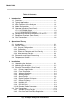
Table of Contents
1 Introduction
1.1 Overview ........................................................................ 1-1
1.2 Typical Applications ....................................................... 1-1
1.3 Main Features of the Analyzer ....................................... 1-2
1.4 Model Designations ....................................................... 1-3
1.5 Operator Interface (Front Panel) .................................... 1-3
1.5.1 UP/DOWN Switch ................................................ 1-4
1.5.2 ESCAPE/ENTER Switch ..................................... 1-5
1.6 Recognizing Difference Between LCD & VFD ............... 1-5
1.7 Equipment Interface (Rear Panel).................................. 1-5
1.8 Gas Connections ........................................................... 1-6
2 Operational Theory
2.1 Introduction .................................................................... 2-1
2.2 Sensor Theory ............................................................... 2-1
2.2.1 Sensor Configuration .............................................. 2-1
2.2.2 Calibration ............................................................... 2-2
2.2.3 Effects of Flowrate and Gas Density ....................... 2-3
2.2.4 Measurement Results ............................................. 2-3
2.3 Electronics and Signal Processing ................................ 2-3
2.4 Temperature Control ...................................................... 2-5
3 Installation
3.1 Unpacking the Analyzer ................................................. 3-1
3.2 Mounting the Analyzer ................................................... 3-1
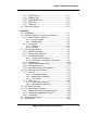
3.3 Electrical Connections (Rear Panel) .............................. 3-3
3.3.1 Primary Input Power .............................................. 3-3
3.3.2 Fuse Installation..................................................... 3-4
3.3.3 Voltage Selections ................................................. 3-4
3.3.4 Analog Outputs ...................................................... 3-4
3.3.5 Alarm Relays ......................................................... 3-6
3.3.6 Digital Remote Cal Inputs ...................................... 3-7
3.3.7 Range ID Relays.................................................... 3-8
3.3.8 Network I/O............................................................ 3-9
3.3.9 RS-232 Port ........................................................... 3-9
3.3.10 Remote Probe Connector ...................................... 3-10
3.4 Gas Connections ...........................................................3-11
3.4.1 Sample System Design .........................................3-13
3.4.2 Pressure and Flow Rate Regulation ......................3-14