
Owner manual


Teledyne Analytical Instruments
Thermal Conductivity Analyzer Installation 3
3-9
ID relay, and the highest range is assigned to the Range 3 ID relay. Range
4 is the Cal Range ID relay.
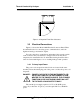
3.3.8 Network I/O
A serial digital input/output for local network protocol. At this print-
ing, this port is not yet functional. It is to be used in future versions of the
instrument.
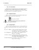
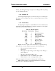
3.3.9 RS-232 Port
The digital signal output is a standard RS-232 serial communications
port used to connect the analyzer to a computer, terminal, or other digital
device. Pin outs are listed in Table 3-3.
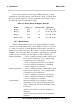
Table 3-3: RS-232 Signals
RS-232 Sig RS-232 Pin Purpose
DCD 1 Data Carrier Detect
RD 2 Received Data
TD 3 Transmitted Data
DTR 4 Data Terminal Ready
COM 5 Common
DSR 6 Data Set Ready
RTS 7 Request to Send
CTS 8 Clear to Send
RI 9 Ring Indicator
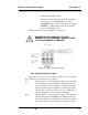
Output: The data output is status information, in digital form, up-
dated every two seconds. Status is reported in the following order:
• The concentration in ppm or percent
• Type of gas
• The range in use (01 = Range 1, 02 = Range 2, 03 = Range 3,
CAL = Range 4)
• The scale of the range (0-100 %, etc)
• Which alarms—if any—are disabled (AL–x OFF)
• Which alarms—if any—are tripped (AL–x ON).
Each status output is followed by a carriage return and line feed.
Input: The input functions using RS-232 that have been imple-
mented to date are described in Table 3-3.