Thermal Conductivity Analyzer OPERATING INSTRUCTIONS FOR Model 2020 Thermal Conductivity Analyzer DANGER HIGHLY TOXIC AND OR FLAMMABLE LIQUIDS OR GASES MAY BE PRESENT IN THIS MONITORING SYSTEM. PERSONAL PROTECTIVE EQUIPMENT MAY BE REQUIRED WHEN SERVICING THIS SYSTEM. HAZARDOUS VOLTAGES EXIST ON CERTAIN COMPONENTS INTERNALLY WHICH MAY PERSIST FOR A TIME EVEN AFTER THE POWER IS TURNED OFF AND DISCONNECTED. ONLY AUTHORIZED PERSONNEL SHOULD CONDUCT MAINTENANCE AND/OR SERVICING.
Model 2020 Copyright © 1999 Teledyne Analytical Instruments All Rights Reserved. No part of this manual may be reproduced, transmitted, transcribed, stored in a retrieval system, or translated into any other language or computer language in whole or in part, in any form or by any means, whether it be electronic, mechanical, magnetic, optical, manual, or otherwise, without the prior written consent of Teledyne Analytical Instruments, 16830 Chestnut Street, City of Industry, CA 91749-1580.
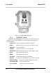
Thermal Conductivity Analyzer Specific Model Information The instrument for which this manual was supplied may incorporate one or more options not supplied in the standard instrument. Commonly available options are listed below, with check boxes. Any that are incorporated in the instrument for which this manual is supplied are indicated by a check mark in the box.
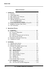
Model 2020 Table of Contents 1 Introduction 1.1 1.2 1.3 1.4 1.5 Overview ........................................................................ 1-1 Typical Applications ....................................................... 1-1 Main Features of the Analyzer ....................................... 1-2 Model Designations ....................................................... 1-3 Operator Interface (Front Panel) .................................... 1-3 1.5.1 UP/DOWN Switch ...............................
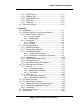
Thermal Conductivity Analyzer 3.4.3 VENT Exhaust ....................................................... 3-14 3.4.4 SAMPLE Gas......................................................... 3-15 3.4.5 REFERENCE Gas ................................................. 3-15 3.4.6 ZERO Gas ............................................................. 3-16 3.4.7 SPAN Gas .............................................................. 3-16 3.5 Testing the System ........................................................
Model 2020 4.8.1 The Set Application Screen ................................... 4.24 4.8.2 The Curve Algorithm Screen ................................. 4-26 4.8.2.1 Checking the Linearization ............................ 4-26 4.8.2.2 Manual Mode Linearization............................ 4-27 4.8.2.3 Auto Mode Linearization ................................ 4-28 4.9 Special Function Setup .................................................. 4-29 4.9.1 Output Signal Reversal ....................................
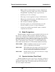
Thermal Conductivity Analyzer Introduction 1 Introduction 1.1 Overview The Analytical Instruments Model 2020 Thermal Conductivity Analyzer, explosion proof, UL and CSA listed for class 1, DIV 1, Groups B, C, and D service, is a versatile microprocessor-based instrument for measuring a component gas in a background gas, or in a specific mixture of background gases. It compares the thermal conductivity of a sample stream with that of a reference gas of known composition.
Model 2020 1 Introduction 1.2 Typical Applications A few typical applications of the Model 2020 are: • Power Generation • Air liquefaction • Chemical reaction monitoring • Steel manufacturing and heat treating • Petrochemical process control • Quality assurance • Refrigeration and storage • Gas proportioning control. 1.
Thermal Conductivity Analyzer Introduction 1 • High resolution, accurate indication of target or impurity gas concentration from large, bright, meter readout. (0-9999 ppm through 0-100 % depending on types of gas involved.) • Standard, proven sensor cell design. • Wide range of custom applications, ranges, and linearization. • Microprocessor based electronics: 8-bit CMOS microprocessor with 32 kB RAM and 128 kB ROM. • Auto and remote calibration capabilities.
Model 2020 1 Introduction Figure 1-1: Model 2020 Front Panel 1.5.1 UP/DOWN Switch Functions: The UP/DOWN switch is used to select the function to be performed. Choose UP or DOWN to scroll through the following list of fourteen functions: • AUTO-CAL Set up an automatic calibration sequence. • PSWD Install a password to protect your analyzer setup. • LOGOUT Locks Setup Mode. • MODEL Displays model and version of analyzer. • SELF-TEST Runs internal diagnostic program, displays results.
Thermal Conductivity Analyzer Introduction 1 • CONTRAST Adjust LCD contrast. Contrast Function is DISABLED (Refer to Section 1.6) • STANDBY Leave analyzer powered, but no outputs or displays. WARNING: THE POWER CABLE MUST BE DISCONNECTED TO FULLY REMOVE POWER FROM THE INSTRUMENT. Subfunctions: Once a Function is entered, the UP/DOWN switch is used to select between any subfunctions displayed on the VFD screen.
Model 2020 1 Introduction • Power Connection 115 or 230 V dc, 50 or 60 Hz. • Analog Outputs 0-1 V dc concentration plus 0-1 V dc range ID. Additional, isolated 4-20 mA dc plus 4-20 mA dc range ID available. • Alarm Connections 2 concentration alarms and 1 system alarm. • RS-232 Port Serial digital concentration signal output and control input. • Remote Valves Used for controlling external solenoid valves, if desired. • Remote Sensor Used for external sensor and thermocouple, if desired.
Thermal Conductivity Analyzer Operational Theory 2 Operational Theory 2.1 Introduction The analyzer is composed of two subsystems: 1. Thermal Conductivity Sensor 2. Electronic Signal Processing, Display and Control. The sensor is a thermal conductivity comparator that continuously compares the thermal conductivity of the sample gas with that of a reference gas having a known conductivity.
2 Operational Theory Model 2020 Figure 2-1: Thermal Conductivity Cell Operating Principle If the thermal conductivities of the gases in the two chambers are different, the Wheatstone bridge circuit unbalances, causing a current to flow in its detector circuit. The amount of this current can be an indication of the amount of impurity in the sample gas, or even an indication of the type of gas, depending on the known properties of the reference and sample gases.
Thermal Conductivity Analyzer Operational Theory 2 2.2.3 Effects of Flowrate and Gas Density Because the flowrate of the gases in the chambers affects their cooling of the heated filaments, the flowrate in the chambers must be kept as equal, constant, and low as possible. When setting the sample and reference flowrate, note that gases lighter than air will have an actual flowrate higher than indicated on the flowmeter, while gases heavier than air will have an actual flowrate lower than indicated.
2 Operational Theory mounted on top of the Motherboard as shown in the figure 5.4. These boards are accessible after removing the back panel. Figure 2-2 is a block diagram of the Analyzer electronics.
Thermal Conductivity Analyzer Operational Theory 2 The Temperature Control keeps the temperature of the measuring cell regulated to within 0.1 degree C. A thermistor is used to measure the temperature, and a zero-crossing switch regulates the power in a cartridgetype heater. The result is a sensor output signal that is temperature independent. In the presence of dissimilar gases the sensor generates a differential voltage across its output terminals.
2 Operational Theory 2-6 Teledyne Analytical Instruments Model 2020
Thermal Conductivity Analyzer Installation 3 Installation Installation of the Model 2020 Analyzer includes: 1. Unpacking 2. Mounting 3. Gas connections 4. Electrical connections 5. Testing the system. 3.1 Unpacking the Analyzer The analyzer is shipped ready to install and prepare for operation. Carefully unpack the analyzer and inspect it for damage. Immediately report any damage to the shipping agent. The four gas fittings that mate with the 1/4 NPT gas ports on the Model 2020, are not included.
3 Installation Model 2020 Hinge Figure 3-1a: Internal Views of the Model 2020 H 3-2 Teledyne Analytical Instruments
Thermal Conductivity Analyzer Installation 3 Figure 3-2: Required Front Door Clearance 3.3 Electrical Connections Figure 3-3 shows the Model 2020 Electrical Connector Panel. There are terminal blocks for connecting power, communications, and both digital and analog concentration outputs. For safe connections, ensure that no uninsulated wire extends outside of the connectors they are attached to. Stripped wire ends must insert completely into terminal blocks.
3 Installation Model 2020 3.3.2 Fuse Installation The fuse block, at the right of the power cord receptacle, accepts US or European size fuses. A jumper replaces the fuse in whichever fuse receptacle is not used. Be sure to install the proper fuse as part of installation. (See Fuse Replacement in chapter 5, maintenance.) 3.3.3 Voltage Selections There is a switch on the interface board, inside the instrument, that selects the working voltage between 230/115 VAC.
Thermal Conductivity Analyzer Installation 3 Figure 3-4: Analog Output Connections Examples: The analog output signal has a voltage which depends on gas concentration relative to the full scale of the range. To relate the signal output to the actual concentration, it is necessary to know what range the instrument is currently on, especially when the analyzer is in the autoranging mode. The signal output for concentration is linear over the currently selected analysis range.
3 Installation Model 2020 To provide an indication of the range, the Range ID analog output terminals are used. They generate a steady preset voltage (or current when using the current outputs) to represent a particular range. Table 3-2 gives the range ID output for each analysis range. Table 3-2: Analog Range ID Output—Example Range Range 1 Voltage (V) 0.25 Current (mA) Application 8 0-1 % H2 in N2 Range 2 0.50 12 0-10 % H2 in N2 Range 3 0.75 16 0-1 % H2 in Air Range 4 (Cal) 1.
Thermal Conductivity Analyzer Installation 3 Actuates when self test fails. To reset a system alarm, call out the set up menue by scroll keys. Use UP/DOWN key to select STANDBY function. Turn off analyzer by pressing ENTER key. Turn analyzer back on by selecting any key. Set ESC key twice. Further detail can be found in chapter 4, section 4-5. DANGEROUS VOLTAGES MAY STILL BE PRESENT AT THIS TERMINALS EVEN IF POWER TO THE INSTRUMENT IS REMOVED. Figure 3-5: Types of Relay Contacts 3.3.
3 Installation Model 2020 priately. See 3.3.9 Remote Probe Connector. (With the –C option, the internal valves operate automatically.) Cal Contact: This relay contact is closed while analyzer is spanning and/or zeroing. (See Remote Calibration Protocol below.) Remote Calibration Protocol: To properly time the Digital Remote Cal Inputs to the Model 2020 Analyzer, the customer's controller must monitor the Cal Relay Contact.
Thermal Conductivity Analyzer Installation 3 ID relay, and the highest range is assigned to the Range 3 ID relay. Range 4 is the Cal Range ID relay. 3.3.8 Network I/O A serial digital input/output for local network protocol. At this printing, this port is not yet functional. It is to be used in future versions of the instrument. 3.3.9 RS-232 Port The digital signal output is a standard RS-232 serial communications port used to connect the analyzer to a computer, terminal, or other digital device.
3 Installation Model 2020 Table 3-4: Commands via RS-232 Input Command Description as Immediately starts an autospan. az Immediately starts an autozero. rp Allows reprogramming of the APPLICATION (gas use) and ALGORITHM (linearization) System functions. st Toggling input. Stops/Starts any status message output from the RS-232, until st is sent again.
Thermal Conductivity Analyzer Installation 3 Figure 3-6: Remote Probe Connector Pinouts The voltage from these outputs is nominally 0 V for the OFF and 15 V dc for the ON conditions. The maximum combined current that can be pulled from these output lines is 100 mA. (If two lines are ON at the same time, each must be limited to 50 mA, etc.) If more current and/or a different voltage is required, use a relay, power amplifier, or other matching circuitry to provide the actual driving current.
3 Installation Model 2020 Figure 3-8: Gas Connections to the Basic Unit There are no gas control valves inside the main chassis. A sample system must be provided for introduction of zero and span gas, as well as sample gas, into the sample path, and for controlling the flowrates through the sample and reference paths of the analyzer.
Thermal Conductivity Analyzer Installation 3 Figure 3-9: Front Panel with optional selector panel (as shown) 3.4.1 Sample System Design Gas Connector and Selector Panels for specific applications are available at additional cost . These panels are optional designed to substitute a standard front panel.
3 Installation Model 2020 NOTE: An additional option is available for SEALED reference application. This option would not have the reference Gas Flow Meter, Piping and Fittings. 3.4.2 Pressure and Flowrate Regulation Appropriate pressure reducing regulators must be installed at all gas supply sources. To minimize flowrate adjustments the pressure regulators on the supporting gas supply cylinders should be adjusted to provide the same output pressure as the sample line regulator.
Thermal Conductivity Analyzer Installation 3 ambient pressures, and pressures must vary no more than the normal barometric changes. Install VENT lines such that water and dirt cannot accumulate in them. Note: If your 2020 has the –V option, see Note at end of Pressure and Flow Rate Regulation, above, for gas vacuum/flow considerations. 3.4.4 SAMPLE Gas In the standard model, sample and calibration gases are introduced through the SAMPLE fitting.
3 Installation Model 2020 3.4.6 ZERO Gas For the ZERO gas, a supply of the background gas, usually containing none of the impurity, is required to zero the analyzer during calibration. For suppressed zero ranges the zero gas must contain the low-end concentration of the impurity. NOTE: Because most cylinder gases are between 99.95 and 99.98% pure, it is highly recommended that the same cylinder of gas be used for both REFERENCE and ZERO gas.
Thermal Conductivity Analyzer Operation 4 Operation 4.1 Introduction Although the Model 2020 is usually programmed to your application at the factory, it can be further configured at the operator level, or even, cautiously, reprogrammed. Depending on the specifics of the application, this might include all or a subset of the following procedures: • Setting system parameters: • Establish a security password, if desired, requiring Operator to log in.
4 Operation Span: Model 2020 Auto, at 10%, every 0 days, at 0 hours Password: TAI 4.2 Using the Controls To get the proper response from these controls, turn the control toward the desired action (ESCAPE or ENTER—DOWN or UP), and then release it. Turn-and-release once for each action. For example, turn-andrelease twice toward UP to move the VFD screen two selections upwards on the list of options (menu).
Thermal Conductivity Analyzer Operation 4 SETUP MODE Span/Zero Off/On Span/Zero Timing PSWD Enter Password Change Yes/No LOGOUT Secure Sys & AnalyzeOnly MODEL Show Model andVersion SELF-TEST Self-Test in Progress AUTO-CAL Auto/Manual SpanSelect SpanValue Set ZERO Auto/Manual ZeroSelect Zeroin Progress ALARMS Select Range Gas Use Range RANGE APPLICATION ALOGORITHM Change Password Verify Password Spanin Progress %/ppm Select Setpoints& Attributes Define Range Select Range Auto/
4 Operation Model 2020 Either control switches you to Setup Mode. Setup Mode switches back to Analyze Mode if no controls are used for more than five seconds. 4.2.1.2 Setup Mode The MAIN MENU consists of 14 functions you can use to customize and check the operation of the analyzer. Figure 4-1 shows the functions available with the 2020. They are listed here with brief descriptions: 1 AUTO-CAL: Used to define and/or start an automatic calibration sequence.
Thermal Conductivity Analyzer Operation 4 13 CAL-INDEPD: Not generally accessed buy the end user. Forces analyzer to be in independent calibration mode. 14 STANDBY: Remove power to outputs and displays, but maintain power to internal circuitry. Any function can be selected at any time. Just scroll through the MAIN MENU with the DOWN/UP control to the appropriate function, and ENTER it. The analyzer will immediately start that function, unless password restrictions have been assigned.
4 Operation Model 2020 a function takes the analyzer back to the previous screen, or to the ANALYZE Function, depending on the function escaped. reproduced, at the appropriate point in the procedure, in a Monospaced type style. Push-button names are printed in Oblique type. 4.3.1 Setting the Display Contrast Function is DISABLED (Refer to Section 1.6) If you cannot read anything on the display after first powering up: 1. Observe LED readout. a. If LED meter reads all eights and dots, go to step 3. b.
Thermal Conductivity Analyzer Operation 4 Call out MAIN MENU, scroll to AUTO-CAL function, and ENTER. A new screen for ZERO/SPAN set appears. ZERO in SPAN in Ød Ød Øh off Øh off Use UP/DOWN Control to blink ZERO (or SPAN), then Enter. (You won’t be able to set OFF to ON if a zero interval is entered.) A Span Every ... (or Zero Every ...) screen appears. Zero schedule: OFF Day: Ød Hour: Øh Use UP/DOWN Control to set a value in days, then ENTER to move to the start-time value in hours.
4 Operation Model 2020 Use the UP/DOWN key to scroll the blinking over to PSWD, and press Enter to select the password function. Either the default TAI password or AAA place holders for an existing password will appear on screen depending on whether or not a password has been previously installed. Enter password: T A I or Enter password: A A A The screen prompts you to enter the current password. If you are not using password protection, press Enter to accept TAI as the default password.
Thermal Conductivity Analyzer Operation 4 Select new password AAA Enter the password using theUP/DOWN and ENTER to scroll through the existing password letters, and the UP/DOWN keys to change the letters to the new password. The full set of 94 characters available for password use are shown in the table below. Characters Available for Password Definition: A K U _ i s } ) 3 = B L V ` j t → * 4 > C M W a k u ! + 5 ? D N X b l v " ' 6 @ E O Y c m w # 7 F P Z d n x $ .
4 Operation Model 2020 4.3.4 Logging Out The LOGOUT function provides a convenient means of leaving the analyzer in a password protected mode without having to shut the instrument off. By entering LOGOUT, you effectively log off the instrument leaving the system protected against use until the password is reentered. To log out, scroll to field of LOGOUT function, and ENTER to logout The screen will display the message: Protected until password entered 4.3.
Thermal Conductivity Analyzer Operation 4 Then the analyzer returns to the initial System screen. 4.3.6 The Model Screen Scroll through the MAIN MENU to MODEL and Enter. The screen displays the manufacturer, model, and software version information. 4.3.7 Checking Linearity with ALGORITHM Use UP/DOWN control to select ALGORITHM, and Enter. sel rng to set algo: > Ø1 Ø2 Ø3 < Use the UP/DOWN Control to select the range: 01, 02, or 03. Then press Enter. Gas Use: H2 N2 Range: Ø 10% Enter again.
4 Operation Model 2020 the curve. The user decides on the number of points, based on the precision required. The manual mode only requires entering the values for each correction point into the microprocessor via the front panel buttons. Again, the number of points required is determined by the user. 4.
Thermal Conductivity Analyzer Operation 4 4.4.1 Zero Cal The ZERO function in the MAIN MENU is used to enter the zero calibration function. Zero calibration can be performed in either the automatic or manual mode. CAUTION: If you are zeroing the Cal Range by itself (multiple application analyzers only), use manual mode zeroing. If you want to calibrate ALL of the ranges at once (multiple application analyzers only), use auto mode zeroing in the Cal Range.
4 Operation Model 2020 TER settling, before it can go back to Analyze. Software zero is indicated by SZero in the lower right corner. ####.## % H2 N2 4 Left=#.### SZero The zeroing process will automatically conclude when the output is within the acceptable range for a good zero. Then the analyzer automatically returns to the Analyze mode. 4.4.1.2 Manual Mode Zeroing Scroll to Zero and enter the Zero function.
Thermal Conductivity Analyzer Operation 4 4.4.1.3 Cell Failure Cell failure in the 2020 is usually associated with inability to zero the instrument with a reasonable voltage differential across the Wheatstone bridge. If this should ever happen, the 2020 system alarm trips, and the VFD displays a failure message. Cell cannot be balanced Check your zero gas Before replacing the sensor: a. Check your zero gas to make sure it is within specifications. b.
4 Operation Model 2020 Use the UP/DOWN key to toggle between AUTO and MAN span settling. Stop when AUTO appears, blinking, on the display. Select span mode: AUTO Enter to move to the next screen. Span Val: 2Ø.ØØ % To begin span Use UP/DOWN key to change the span setting value. ENTER will move the blinking field to units (%/ppm). Use UP/DOWN key to select the units, as necessary. When you have set the concentration of the span gas you are using, Enter to begin the Span calibration. ####.
Thermal Conductivity Analyzer Operation 4 plings and displays this difference as Slope on the screen. It takes several seconds for the first Slope value to display. Slope indicates rate of change of the Span reading. It is a sensitive indicator of stability. ####.##% H2 N2 Slope=#.### Span When the Span value displayed on the screen is sufficiently stable, press Enter.
4 Operation Model 2020 In failsafe mode, the alarm relay de-energizes in an alarm condition. For non-failsafe operation, the relay is energized in an alarm condition. You can set either or both of the concentration alarms to operate in failsafe or non-failsafe mode. 3. Are either of the alarms to be latching? In latching mode, once the alarm or alarms trigger, they will remain in the alarm mode even if process conditions revert back to non-alarm conditions.
Thermal Conductivity Analyzer Operation 4 AL1: 1ØØØ ppm HI Dft:N Fs:N Ltch:N Five parameters can be changed on this screen: • Value of the alarm setpoint, AL1: #### • Out-of-range direction, HI or LO • Defeated? Dft:Y/N (Yes/No) • Failsafe? Fs:Y/N (Yes/No) • Latching? Ltch:Y/N (Yes/No). • To define the setpoint, use the UP/DOWN key while screen is blinking over to AL1: ####. Use the UP/DOWN key to change the number. Holding down the key speeds up the incrementing or decrementing.
4 Operation Model 2020 In the AUTO screen, you are further allowed to select which gas application (PREVIOUSLY defined in APPLICATION function) to run. 4.6.1 Manual (Select/Define Range) Screen The Manual range-switching mode allows you to select a single, fixed analysis range. It then allows you to redefine the upper and lower limits, for the range.
Thermal Conductivity Analyzer Operation 4 automatically shifts to the next higher range. If the concentration falls to below 85% of full scale of the next lower range, the instrument switches to the lower range. A corresponding shift in the DC concentration output, and in the range ID outputs, will be noticed. The autoranging feature can be overridden so that analog output stays on a fixed range regardless of the contaminant concentration detected.
4 Operation Model 2020 4.6.3 Precautions The Model 2020 allows a great deal of flexibility in choosing ranges for automatic range switching. However, there are some pitfalls that are to be avoided.
Thermal Conductivity Analyzer Operation 4 the Escape button in many cases also switches the analyzer back to the Analyze function. Alternatively, if you leave your analyzer on MAIN MENU screen within 5 seconds without touching any key, it will automaticaly return to analyze function. If the analyzer is in subfunction mode, in most cases, it will automaticaly return to analyze mode within 10 minutes.
4 Operation Model 2020 4.8.1 The Set Application Screen The Set Application screen allows reprogramming of the three analysis ranges and the calibration range (including impurity gas, background gas, low end of range, high end of range, and % or ppm units). Original programming is usually done at the factory according to the customer’s application. It must be done through the RS-232 port using a computer running a terminal emulation program.
Thermal Conductivity Analyzer Operation 4 Use the UP/DOWN key to increment/decrement the range number to 01, 02, 03, or CAL, and Enter. Imp: FR:Ø H2 Bck: TO:1Ø % N2 Use the UP/DOWN key to increment the respective parameters as desired. Use the ENTER to move from Imp: (impurity) to Bck: (background), FR: (from—lower end of range), TO: (to—upper end of range), and PPM or %.
4 Operation Model 2020 4.8.2 The Curve Algorithm Screen The Curve Algorithm is a linearization method. It provides from 1 to 9 intermediate points between the ZERO and SPAN values, which can be normalized during calibration, to ensure a straight-line input/output transfer function through the analyzer. (Before setting the alogorithm curve, each range must be Zeroed and Spanned).
Thermal Conductivity Analyzer Operation 4 Select algorithm mode : AUTO There are two ways to linearize: AUTO and MANUAL: The auto mode requires as many calibration gases as there will be correction points along the curve. The user decides on the number of points, based on the precision required. The manual mode only requires entering the values for each correction point into the microprocessor via the front panel buttons. Again, the number of points required is determined by the user.
4 Operation Model 2020 Dpt 0 INPUT Ø.ØØ OUTPUT Ø.ØØ Repeat the above procedure for each of the data points you are setting (up to nine points: 0-8). Set the points in unit increments. Do not skip numbers. The linearizer will automatically adjust for the number of points entered. When you are done, ESCAPE. The message, Completed. Wait for calculation, appears briefly, and then the main System screen returns. To end the session, send: st st to the analyzer from the computer. 4.8.2.
Thermal Conductivity Analyzer Operation 4 6. Repeat step 5 for each of the special calibration gases, from the lowest to the highest concentrations. Escape when done. To end the session, send: st st to the analyzer from the computer. 4.9 Special Function Setup CAUTION: The programming functions of the output signal reversal, polarity reversal and gain preset are configured at the factory to the users application specification.
4 Operation Model 2020 argon in nitrogen, normally zero gas of this application requires 40% argon in nitrogen. However, 100% of nitrogen can be used to zero the analyzer. In this case, the output offset is not needed to setup. For linear output the accuracy will access successfully within +/-1% off. But, if the application is analyzing the sample gas that is not linearly, the accuracy of the analyzer may not meet the specification.
Thermal Conductivity Analyzer Operation 4 For nonlinear application, signal that produces from the termal conductivity, will not correspond to the actual gas concentration. The amplification of each range will not agree, therefore, the gain must be preset in order for the signal to read linearly. To set the gain, the following must be performed in sequence. NOTE: Before setting up this feature, you must have a span gas containing 90%-100% of the lowest range of the analyzer. 1.
4 Operation 4-32 Model 2020 Teledyne Analytical Instruments
Thermal Conductivity Analyzer Maintenance 5 Maintenance 5.1 Routine Maintenance Aside from normal cleaning and checking for leaks at the gas connections, routine maintenance is limited to replacing fuses, and recalibration. For recalibration, see Section 4.4 Calibration. WARNING: SEE WARNINGS ON THE TITLE PAGE OF THIS MANUAL. 5.2 System Self Diagnostic Test Use UP/DOWN key to enter the SELF-TESY function.
5 Maintenance Model 2020 2 3 Amplifier output doesn't match test input Both Failed >3 Open gain resistor Cell 5.3 0 OK 1 Failed (open filament, short to ground, no power.) 2 Unbalance (deterioration of filaments, blocked tube) Fuse Replacement The 2020 requires two 5 x 20 mm, 4 A, T type (Slow Blow) fuses. The fuses are located inside the explosion proof housing on the Electrical Connector Panel, as shown in Figure 5-1. To replace a fuse: 1. Disconnect the Unit from its power source. 2.
Thermal Conductivity Analyzer 5.4 Maintenance 5 Major Internal Components The Cell Compartment and Front Panel PCBs are accessed by unlatching and swinging open the front panel, as described earlier. The balance of the PCBs are accessed by removing the rear panel retaining screws and sliding out the entire subassembly. See Figure 5-3, below. The major electronic components locations are shown in Figure 5-4 (with Cell Compartment removed for clarity).
5 Maintenance Model 2020 Figure 5-3: Rear Panel Retaining Screws Figure 5-4: Locations of Printed Circuit Board Assemblies 5-4 Teledyne Analytical Instruments
Thermal Conductivity Analyzer Maintenance 5 See the drawings in the Drawings section in back of this manual for details. 5.6 Cell, Heater, and/or Thermistor Replacement The Thermal Conductivity Cell, with its Heater and Thermistor, is mounted inside the insulated cell compartment, just behind the analyzer's front panel access door.
5 Maintenance Model 2020 To remove the Cell Compartment: a. Disconnect gas and electrical connections to the analyzer. b. Remove analyzer from its mounting, and remove gas fittings from the gas ports on the bottom of the analyzer, so that nothing projects from the ports. c. Remove the Cell Compartment retaining screws identified in Figure 5-5. You will have to unlatch and swing open the front panel door to remove the front screws. d.
Thermal Conductivity Analyzer Maintenance 5 b. Remove the two screws holding the front mounting bracket— they also hold the Cell Block Cover to the Cell Block—and then pull off the cover. c. Turn the uncovered Cell Block assembly over so that the bottom faces you. The black rectangular block with four screws is the Heater Block. Separate the Heater Block from the Cell Block by removing the four screws. Leave the Heater Block electrical connections connected. d.
5 Maintenance Model 2020 c. Turn the uncovered Cell Block assembly over so that the bottom faces you. The black rectangular block with four screws is the Heater Block. d. The Heater is fastened to the Heater Block by a set screw as well as the silicone sealing compound. The Thermistor is fastened only by the silicone sealer. (1) To remove the Heater, use a 1/16 ″ Allen wrench to loosen the Thermistor set screw.
Thermal Conductivity Analyzer 5.7 Maintenance 5 Cleaning If instrument is unmounted at time of cleaning, disconnect the instrument from the power source. Close and latch the front-panel access door. Clean outside surfaces with a soft cloth dampened slightly with plain clean water. Do not use any harsh solvents such as paint thinner or benzene. For mounted instruments, DO NOT wipe the front panel while the instrument is controlling your process. Clean the front panel as prescribed in the above paragraph.
5 Maintenance 5-10 Model 2020 Teledyne Analytical Instruments
Thermal Conductivity Analyzer Appendix Appendix A-1 Specifications Ranges: Three ranges plus a cal range with linearizer, field selectable within specified limits (application dependent) and Auto Ranging Display: 2 line by 20 alphanumeric VFD accompanied by 5 digit LED display Accuracy: ±1% of full scale for most binary mixtures at constant temperature ±5% of full scale over operating temperature range once temperature equilibrium has been reached Response Time: 90% in less than 65 seconds System Operati
Appendix Models 2020 System Power Requirements: 115/230 VAC, 50-60Hz Cell Material: Nickel plated brass block with nickel alloy filaments and stainless steel and plates O/P Interface: Full duplex RS-232, implement a subset of Tracs Command Mounting: Explosion-Proof Housing, Bulkhead Mounting.
Thermal Conductivity Analyzer Appendix A-2 Recommended 2-Year Spare Parts List Qty Part Number Description 1 D67472 Back Panel Board 1 C62371B Front Panel Board 1 C65098A Preamplifier Board 1 C62365D Main Computer Board 2 F1295 Fuse, 4 A, 250 V, 5 × 20 mm, T—Slow Blow _____________________ * Order one type only: US or European, as appropriate.
Appendix A-4 Models 2020 Teledyne Analytical Instruments