
User guide

Teledyne Analytical Instruments
Thermal Conductivity Analyzer Part I: Control Unit
Part I 3-3
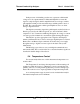
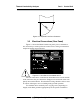
Figure 3-2: Required Front Door Clearance
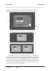
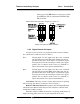
3.3 Electrical Connections (Rear Panel)
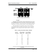
Figure 3-3 shows the Model 2010A rear panel: power, communica-
tion, alarm relays, remote probe and control valves, analog concentration
output and analog range indicators.
Figure 3-3: Rear Panel of the Model 2010A
For safe connections, ensure that no uninsulated wire extends outside
of the connectors they are attached to. Stripped wire ends must insert com-
pletely into terminal blocks. No uninsulated wiring should be able to come
in contact with ngers, tools or clothing during normal operation.
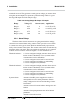
Use shielded cable, nominally 20 to 22 gauge wire (depending on
length), with shield grounded appropriately for the specic installation.
H