
User guide

2-4 Part I
2 Operational Theory Model 2010A
Teledyne Analytical Instruments
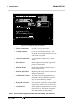
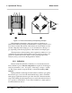
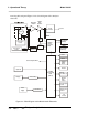
removing the back panel. Figure 2-2 is a block diagram of the Analyzer
electronics.
Figure 2-2: Block Diagram of the Model 2010A Electronics
Thermistor
Sensor
Heater
Temperature
Control
Fi ne
Adjustm ent
Coarse
Adjustment
Aut o-
Range
M
U
X
A to D
Convert er
Digitial to
Analog
Conver ter
(DAC)
0-1 V dc
Concentration
and Range
4-20 mA dc
Concentration
and Range
Differential
Amplifier
Var i a bl
e
Gai n
Amplifier
Central
Processing
Unit
(CPU)
Alarm 1
Alarm 2
System
Failure
Alar m
RS- 232
Range
Contacts (4)
External
Val v e
Cont rol
Remote Span
Control
Remote Zero
Contr ol
Cal
Contact
Keyboa rd
Displays
Processing
Selt-Test Signal to MUX
Powe r
Supply
A to D Conv
To CPU
Temperature
Control
Heat er